- 2021-12-1
- temporary jobs remote
You may have to replace the ignition / lightswitch then you may need to open up the wiring section that is taped up with blue tape to trace the red wire or any others that may be damaged. foretravel motorhomes repair and technical help. . Unprotected ignition system, starter system, alternator . ... M3030011800023 TSB Revision CIRCUIT DIAGRAMS BRAKE WARNING LIGHT, OIL PRESSURE WARNING LIGHT, FUEL WARNING LIGHT 90-83 TSB Revision 90-84 CIRCUIT DIAGRAMS POWER WINDOWS … 67-72 wiring diagram. Ammeter. OD was operative only in top up to TS6266, may, 1955. a. [/ QUOTE ] If that's a single wire pressure switch then a buzzer would have go from the ignition switch to the pressure switch ie in parallel with the low oil pressure warning light. 2Control box23Horn-push44LH rear flasher. Nice set of wiring diagrams to take to the garage. Version. From here it runs to the ignition/starter switch. Please click on the diagram for a larger image in a separate window. 1967 Master Wiring Diagram: 1967 F-100 thru F-350 ignition, charging, starting, and gauges: ... 1969 F-100 thru F-350 dual brake warning light: 1968 F-100 thru F-350 horn circuit ... using circuit 282 (green wire) for right-hand lights and circuit 283 (yellow wire/black stripe) for left-hand lights. Stop Lights Page L-3 4. sw Sq A/T NO NC IN THIS BOOKLET ... WIRING DIAGRAM BATTERY TERMINAL OF IGNITION SWITCH TERMINAL OF IGNITION SWITCH ACC TERMINAL IGNITION SWITCH 50 SYSTEM CIRCUIT HEADLIGHTS HEADLIGHTS RETRACTABLE CLEANER WARNING INDICATOR INSTRUUENT LIGHTS RIGHT TURN INDICATOR LEFT TURN tNOlCATOR ... WIRING DIAGRAM . You will need to refer to this diagram for the following notes. On the bottom of the lid of the fuse block is a diagram showing the numbers of the pins along with which relay goes where. Complete wiring for the '69 looks like this. the ignition). Ignition timing light circuit diagram. The Number 1 wire on the 10- or 12-SI is connected to the charge warning light on the dash. the alternator to read voltage at some other point than the battery. The one to the ignition only gets momentary 12v when you turn the switch to activate the starter makes no sense if it only gets power at that point. The "B" is from the battery, red or orange with a stripe. IGNITION SWITCH Brass terminals on switch Wiring Diagram For 4 Position Universal Ignition Switch Product Code P00940 Headlights Page L-1 2. 312V Battery24Radio45LH front flasher. Switch on the ignition. 1Alternator22Twin windtone horns43Flasher unit. See diagram B2 for later wiring diagram. 1987 1996 f150 larger f series trucks 1987 headlamp switch wiring diagram im in the process of wiring my 1946 ford pickup hot rod using a 1987 f150 headlight switch. It should be noted that the wiring diagram shown here is physically correct for the switch, but the terminals on the base are marked incorrectly. The instructions are shown below and can be printed off. . Stator to Regulator (Charging Circuit) Yellow with Red Stripe : Otherwise, the structure won’t work as it should be. Has them for $139.62 and includes h, lights, wiring, etc. 69 MUSTANG WIRING DIAGRAM-1 - Drawing A. Power Mirrors Page A-3 4. Fog Lights Optional 24 Hand rake Warning Light. Drill a 14mm hole, slide the warning light into the hole and it clicks into place. Connect the two wires to earth and a terminal of the ignition switch made live by turning the ignition on. Both wires are 1m long and should suit most vehicles. Included is a wiring diagram that is very similar to one found in the Ownerʼs Manual. An American alternator should be Ok, the one you want must have the thick and thin spade connectors with the warning light … warning light (Section C) Legend in the parenthesis ) indicates the refer- ence section. In general, if the charging system is working normally, the warning light should glow when the ignition is switched on and then extinguish when the engine is started. Having to stow the table and table leg in the intended compartment back under one of the twin beds is super-inconvenient, particularly when the beds are configured together as a king. Oil pressure warning light Ignition warning lamp 'FASTEN BELTS' warning lamp Luggage compartment lamp Ignition coil Panel lamp Fuel gauge Lighting switch ... WIRING DIAGRAM: 1978 and later California Specification 48 GN 81 82 SNB 047 C 24 BWB 51 50 26 wï . Headlights Page L-1 2. gauge, seat belt warning light Diagram 5 Warning lights and gauges Diagram 6 Exterior lighting Diagram 7 Exterior lighting continued, buzzer, interior lighting the \citroencv offers a standard advance curve as cv wiring diagrams page. Mahindra diesel ignition switch wiring diagram . Back to FAQ Home. Vehicle Wiring.Relocate table storage. WARNING FLASHER & SWITCH INSTRUMENT LT AMMETER R DIRECTION INDICATOR INSTR LIGHT TEMPERATURE GAUGE IGNITION SWITCH CIGAR LIGHTER ... 66 Mustang Wiring Diagrams (Colorized)1.pdf Author: George Flew Created Date: the ignition). First the ignition is turned on, and current flows from the battery, through the ignition switch, the ignition warning light, a link inside the control-box, and through the low-resistance armature winding of the dynamo so lighting the warning light. Yes. Listed below is the vehicle specific wiring diagram for your car alarm, remote starter or keyless entry installation into your 2008-2011 Jeep Liberty . Midget (Series "TD) and (Series "TF") Workshop Manual, particularly the diagram on page N.23. Scully Grounding System Wiring Diagram. V1203: pump cut-off light. AYGO Interior Light Circuit Diagram AYGO Dashboard Switch Lighting Schematic AYGO Reversing Light Wiring Diagram AYGO ABS Wiring Diagram Open. Power Mirrors Page A-3 4. V1702: reverse drive warning lamp. — Spare Starter motor j n o = Trailer Sidelight = Foglight Main beam Spare … Rear Window Defogger Page A-1 2. One brake light fitted up to TS15601, May, 1957, for US market. V1200: injection test warning lamp. No charge Brake system Hand brake = Seat belt Spare Direction ind. Wiring diagrams for a TO-20 with the original warning light, and one with an ammeter are available on our website. 25 A-Battery B-Starter D – IgnitionStarter Switch S88 – Fuse Strip main fuse T1 – 1-Pin Connector black engine compartment right T10a – 10-Pin Connector brown. Oil pressure switch to warning light or gauge. G ws Radio/ cassette 5A fuses Ignition switch ws Glow plugs (non turbo) wo I-GP GW GR Voltage sensitive switch BS Glow plugs (turbo) YB a b e = Spare Low oil press. Tail light wiring: '68 thru '72 Beetle showing wire colors. Wiring Harness, Connectors, Switches, Relays & Breakers, JEGS. CABLE COLOUR CODE—WIRING DIAGRAMS. Ignition and starter wiring highlight: 1971 : Merged version With rear window defroster and ambulance fans Original factory diagrams: (fuse box is depicted wrong) Merged version of the above Current track version of wiring diagram Headlights highlight Brake lights highlight Turn signals highlight 4-way flashers highlight Ignition highlight The wire runs from the alternator through the bulkhead and up to the warning light mounted in the dashboard. suzuki outboard ignition switch wiring diagram – You’ll need an extensive, expert, and easy to know Wiring Diagram. Dynamo. Thermostart. Check this by turning on the ignition and disconnecting the warning light wire. . Listed below is the vehicle specific wiring diagram for your car alarm, remote starter or keyless entry installation into your 2004-2005 Dodge Ram . WIRING Toyota Toyota RAV4. Here we have Chevrolet Wiring Diagrams and related pages. Omc ignition switch wiring diagram. 99; Britax 605. This information outlines the wires location, color and polarity to help you identify the proper connection spots in the vehicle. 6Starter switch27Panel lamp48RH rear flasher. by Anna R. Higginbotham. Inspect the wire for any chafing against the bodywork and repair it with insulating tape. Power Windows Page A-2 3. Automatic Light Turn-off Page L-4 5. And among those are as follow: battery, windshield wiper switch, light switch, turn signal and head light dimmer switch, emergency flasher switch, safety belt locks, back-up light switch, fuel gauge vibrator, high beam warning light, transmission switch for safety belt system, fuel gauge … 69 MUSTANG WIRING DIAGRAM-2 - Drawing B. Drill a 14mm hole, slide the warning light into the hole and it clicks into place. Sub-section 01 (WIRING DIAGRAMS) AOOO 004 046 Tab Housing seen from wires side IMPORTANT: On all electric start models the snow mobile frame carries a negative direct current (DC) while all alternating current (AC) consumers (lights, heated grips, fuel gauge, etc) utilize a separate ground wire. If the gauge does register, the sender unit is bad. Only one switch fitted prior to this change. Three-wire Alternator: This setup uses a battery wire, ignition/warning light wire and voltage sensing wire, Three wires. w/o carb heater) (light blue in 1970's) White/ Pink. 4Ignition warning light25Panel lamp46Flasher switch. Check if you also have the Parking Brake lamp. When the engine is started and the speed of the generator is sufficient, the light will go out, indicating that you are not running off the battery. Wiring diagram ws white sw black ro red br brown gn green bl blue gr grey li lilac ge yellow IgnitionStarter Switch main fuse or orange rs pink Audi A4 No. cold runing light to mechanical switch on choke cable (vech. Ignition Coil wiring diagram. And among those are as follow: battery, windshield wiper switch, light switch, turn signal and head light dimmer switch, emergency flasher switch, safety belt locks, back-up light switch, fuel gauge vibrator, high beam warning light, transmission switch for safety belt system, fuel gauge … 13-16 Wiring diagrams KEY TO WARNING LIGHTS LH speaker BW . Wiring Diagrams 1. (its missing the black/yellow=to front parking lights, the rest is a match. Power Windows Page A-2 3. 16A.the wiring diagram shows the position of the wires in harnesses and the the key is the same for both wiring diagram and circuit diagram. 42 ack-up Light Switch That's where dashboard warning lights come in. (See note below.) The gauge should slowly climb to hot and the test light should glow. (ED: The ignition light is used to tell when a generator (or alternator) is charging the battery. June 11, 2021 on Ignition Interlock Wiring Diagram. 39 Head Light Switch. Wiring Diagrams & Harnesses for Ford Tractors . V1700: temporary fault warning lamp. The Alternator wiring may have to be modified to accept a different type from a Lucas 16ACR type which I used. The ignition warning light on my TR4 has never worked. Primary Ignition Resistance Bypass Instrument and Panel Lights, (Fused No. THE LIGHTS ON WHEN THE IGNITION IS ON. T4 BASE WIRING DIAGRAMS Transporters - from May 1999 on ... in interior light wiring harness 128 Connection -1-, in interior light/door contact switch wiring ... rs = pink u2,'6 r 8b/7 Page 12 of 22 No. Ignition switch wiring diagram diesel engine.A wiring diagram is a streamlined traditional pictorial representation of an electric circuit. Understanding Diagrams Page U-1 Lighting Systems 1. GENERATOR WARNING LAMP. for citroën > cv, cv, dyane, ami, mehari.. wiring diagram cv. ET-101P - SIMPLIFIED WIRING DIAGRAMS, Booklet - (1-MB pdf) A 13-page PDF print file including ET-101 through ET-101J below. Welcome to the forum Martin. 41 rake Light Switch. The ignition warning light is lit when the ignition is switched on but the engine is stopped by 12v coming from the ignition switch, and an earth from the IND terminal on the alternator. Another view showing the actual plug/socket wiring to switches. Wiring Diagrams 1. When you first turn the ignition off, you have disconnected battery voltage from the switch side of the warning light, but it still has full charging voltage from the dynamo side. However also on the ignition switch side of the warning light are the feeds from the ignition switch to the ignition coil, fuel pump, instruments etc. COIL HEAD LIGHTS. each Diagram contains standard wiring schematic & wiring upgrades, including: Wire color chart, Battery tender install, push button starter, ignition switch replacement (3), msd ignition install, hella horns, standard & high torque starter installations (4), headlight warning buzzer, manual fan … Turnsignals & Hazard Page L-2 3. If the warning light stays on, the wire is earthing somewhere. The Universal fit Charge Warning light with 10mm RED LED - £11.75. ... Wire it via the ignition switch. Something is causing the wire to overheat. 1972 chevy truck ignition switch wiring diagram. 1976 I have a 2-wire plug for the alternator, a bracket, a wide belt with the proper length and a wide pulley for the alternator. Fuse colours 30 A- 25 A- 20 A- 15 A- IOA- 7.5 A- green white yellow blue red brown beige lila 5Ignition switch26Panel lamp47RH front flasher. To ignition system To starter motor solenoid To accessories e.g. … BATTERY-+ Positive Earth. Toyota RAV4 2008 Electrical Wiring Diagrams. doubt that the grounding systems at your terminals are performing their The Scully Groundhog, when wired as a self-proving system, cannot be fooled by. Ignition switch to radio fuse. The generator is doing it's job and … V1300: engine diagnosis warning lamp. I decided to try to track down the problem this evening. That was about 200-250 miles before my dashboard lit up today. Next, the engine is started, the dynamo starts to turn, generating a small voltage from its residual magnetism. 1 4runner electrical wiring diagram 23e 2 7 am2 8 6 b- w am1 4 st2 ig2 2 ig1 p 1 park/neutral position sw 3e 2 1 3 5 ... charge warning light [comb. . 5a sta 10a gauge w * 1 : w/ daytime running light ... b- l l- y g- w b- y w- b b- r b- r b- r b- r b- r br to engine control module <2-8> b- r b- r b- r ignition coil no. V1701: forward drive warning lamp. Starter Solenoid Switch. title: project wiring diagrams.pub author: admin1 created date: V1150: pre-heat warning lamp. Some cars also had courtesy lights below the dash. Wiring Diagram. If the wire is completely severed or badly chafed it will need replacing with a whole new section. 37 Ignition-Starter Switch. Starter switch to starter solenoid or inhibitor switch Lambretta light switch wiring diagram. Wiring. White/ Blue. plug board Release contacts Starter valve Thermo-time switch Brake fluid indicator tamp switch Cigar lighter Turn Signal and warning flasher relay Horn contact Combination switch a Turn signal 'amp switch b Headlamp flasher switch c Dimmer switch Ignition Warning Light. Automatic Light Turn-off Page L-4 5. Indicator and Front Direction Light R.H. Indicator and Front Direction Light 1975 Chevy Headlight Switch Wiring Diagram Experts Wiring Diagram. They is a 6 pin plug with red black and brown on bike and an 6 pin plug with red black green blackwhite on ignition switch all of them in completely different positions. White/ Red. ET-101 - SIMPLIFIED WIRING DIAGRAMS, Base Page ET-101A - SIMP ABBREVIATIONS for Electrical Diagrams ET-101B - SIMP Charging circuit ET-101C - SIMP Starter circuit Oddly enough, the Ignition Warning Lamp has very little to do with ignition, but refers mostly to operation of the generator and control box. meter] 5 3e b b 1 7. . The Petrol Warning Light is wired between the A4 terminal of the fuse box and the Petrol Tank Unit where it is closed to earth when the petrol gets low. Using a voltmeter, I determined that I don't have a circuit connection between the control box (terminal D) and the lamp. Wiring Diagram for Outboard Ignition Switch Best Evinrude Ignition. That serves as a bulb test, so you know the warning will work. Switch - Ignition (see product data sheet for wiring diagram) View Product Specifications. 2-Wire Sensor Systems ( Like the Civacon ROM II or Scully IntelliCheck 2 Ground Bolt wired to Pin # 9. However, as I explained in my initial post, my alternator has 2 wires (not 3 wires), one going to the battery via an ammeter and the other going to the warning light. 206 wiring Peugeot diagrams Key to circuits Diagram 1 Information for wiring diagrams Diagram 2 Starting, charging, horn, pre/post-heating Diagram 3 Pre/post heating, engine cooling fan Diagram 4 Engine cooling fan, temp. Estimated delivery wed may 22. In the 1972 Beetle and Super Beetle Wiring Diagrams, you will see the details parts of it. . LIGHT SWITCH STARTER SOLENOID STARTER. The ignition lamp can be useful, sometimes. 30 High eam Indicator Light On Tachometer 31 Parking Light Indicator Light. Component Index, Connector Code, and Wire Color Code . You will also need a double pole on/off switch such as 020.021 or 020.251 and a 5 watt warning light. Ignition switch or starter switch to starter solenoid. Wiring descriptions and terminology used in the following discussion are taken from wiring diagrams found in Section N of The M.G. Weight: 0.56lbs. Can be “straight' wired system (diagram next page) . Tail light wiring: '73 thru '79 Beetle showing wire colors. Diagrams and such: 57_ford_wiring - Drawing A. Product Specifications. Wiring Diagrams: 57 Chevy -150-210 Belair wiring diagram - Drawing A 1964 Chevelle Wiring Diagram: Figure A Figure B 1965 Chevy II Wiring Diagram: Figure A Figure B 1965 Impalla Wiring Diagram: Figure A Figure B 1967 Chevy-AC-Assembly Manual - Drawing A 1968 Camero wiring - in a .PDF file Suitable for Make/Model. Possibly some of the mysterious wiring could come from the sportslamp switch above the radio or is a provision for it. There is also a wiring diagram to install a Delco alternator though I suggest you retain the original 6 volt positive ground electrical system. hazard warning lights, remove key buzzer instrument lights.. Perkins diesel engine wiring harness and diagram The front face of the original Perkins control panel,which is fitted with VDO gauges,oil pressure,rev, counter and water temprature,charge warning light,I have added an instrument light on/off switch and a remote cockpit 12volt supply plug. 1972 Seat Warning Lamp In Cluster Fuse Block Gauges 10 Amp Ignition Switch Belt Warning 1972 SEAT BELT REMINDER SYSTEM SCHEMATIC System B/W … A kinetic energy recovery system for bicycles, which can provide assistance to riders by harvesting energy during low-impact periods. Wired as you suggest when the oil pressure drops the contacts in the pressure switch will close, to illuminate the bulb, and simply short out the buzzer. Distributor. HOW-TO-USE THESE WIRING DIAGRAMS Page numbering The wiring diagrams identified with page numbers “1”, “2”, etc. These Charge Warning Lights work on any vehicle where turning the ignition on connects the battery to the ignition coil (s) or electronic ignition system. NOT suitable for magneto/magdyno equipped vehicles unless connected to the charging circuit with a dedicated on/off switch. Oil Pressure Indicator ombi-Instrument 28 Generator Warning Light. WU B B N we G p R BLACK BLUE … John Deere Gator I 11 Wiring Harness John Deere. OEM … This information outlines the wires location, color and polarity to help you identify the proper connection spots in the vehicle. AMMETER--+ Fuse 15A + IGNITION SWITCH. For ... (Fuel Warning Light) to Fuel Tank Switch 25 41 14 Dash (Ignition Warning Light) to Regulator (D) 25 73 12 Regulator (D) to Generator (Armature) Voltage sensing is used when you want. Mar 8, 2020. Daytime Running Lights Page L-5 Accessories Systems 1. 5mm wire 4mm wire 2. radio, lights, cigar sockets etc. I … Parking and side marker lights, engine and luggage Compartment lights, clock and cigarette lighter lights, Power windows Air Conditioning .. Wiring DiagramsWiring Diagrams S1, S1A, S1B, S2, TC, SPCLS1, S1A, S1B, S2, TC, SPCL . Turnsignals Hazard Page L-2 3. Julian Eyre is raising funds for BiKERS: Bicycle Kinetic Energy Recovery System on Kickstarter! Check as follows: Remove the Green/Blue wire from the sender unit in the cylinder head. 44 Circuit) Tail and License Lamp, Forward Side Marker Lamps Tail, Clearance and Marker Lamps (Trailers) Dimmer Switch Feed Headlamp, High Beam Headlanp, Low Beam Front Parking Lamps L.H. Find this Pin and more on Volks by Jeff Smith. 29 Turn Signal Indicator Light. . This earth comes through the field winding and its slip-rings and brushes, from the field terminal of the voltage regulator. Indicates the connector number shown in the wiring harness configuration diagram. S.163018 - Ignition Key. 1964 F-100 Wiring locator Drawing A. Vespa Wiring Diagrams Vespa Vespa Super Trailer Light Wiring . View Suitable For View OEM Part Numbers. Internal circuit details of later brake system dash warning lights. 65 Mustang wiring diagram-2 Drawing B. In the 1972 Beetle and Super Beetle Wiring Diagrams, you will see the details parts of it. wiring diagrams 2002 . Troubleshooting the ignition warning light, How a Car Works. Swi tch ABBREVIATIONS USED Abbr. Also Note: Wire sizes on these and most other wiring diagrams are printed on the wire in mm 2.For Americans who express wire sizes in gauges, see this Wire Size Conversion Table.. Connect one end of your test light to the terminal on this wire, the other end to ground. Connect the two wires to earth and a terminal of the ignition switch made live by turning the ignition … Rear Window Defogger Page A-1 2. Ignition Coil DIAGRAM NW NW NW NG DIAGRAM Ferguson MF 35 fitted with Diesel Engine (B) Two—6 Volt Batteries. Lights Horn Pilot light 1 Power 4 Starter Solenoid 3 Glow Plug 4mm wire 4mm wire 2.5mm wire 2.5mm wire 2.5mm wire Agriline Diesel Massey Ferguson 35 Wiring Diagram Diesel 3 Cylinder with alternator 674 96AH battery Insulate wires with a good quality insulation tape and place in protective flexible auto wire sleeve Contributed by Neil Reitmeyer, Rob G, Don & Derek Barkley, Dan Dibbens, Ed Gooding, and Tyler Neff • 9N/2N Wiring Diagrams . contents series e-s page 3 s 50 page 4 s 50 psa page 5 s 80 page 6 s 100 page 7 t 40 psa page 8 t 40 x+ page 9 t 50 page 10 t 50 x+ page 11 ... diagram for auto start aoost dose stat "ash pumps . Wiring diagram ws= white sw = black ro = red br = brown gn = green bl = blue gr = grey li = lilac ge = yellow Ignition/Starter Switch, main fuse or = orange rs = pink Audi A4 No. Turnsignals & Hazard Page L-2 3. F D. DISTRIBUTER. warning light how a car works, dash wiring spec identification transit mk7, ford ignition switches 57 79 truck 61 67 econoline, model a ford switch ebay, schematic diagram and worksheet resources fishgarden co, 1928 1929 ... model a ford ignition wiring wiring diagram pictures, This article includes the following subtopics: Engine Compartment Wiring my ignition switch male term, yellow, red/green (something with ignition) green/red & a brown wire that says resistor wire on it. Stop Lights Page L-3 4. ... IGNITION LIGHTS [61] TOP VIEW E K U T S START RELAY 15A ACCESSORY INSTRUMENTS SPARE T K U S E 15A 15A 15A 15A 15A AB R P G H D C J I SECURITY INDICATOR BN/V BN/V [83A] [83B] BK BK BK BK BK However also on the ignition switch side of the warning light are the feeds from the ignition switch to the ignition coil, fuel pump, instruments etc. This allows current to flow from the dynamo, through the warning light and those components to their earths. Convert Your Ac Ignition To Full Dc For Pennies Workshop. I found a diagram showing one wire going to the ignition switch the other into the printed circuit I assume to the light. Do you have a wiring diagram for this type of alternator. Here it is mounted in a '70 with a little custom wiring. John Deere Gator Wiring Harness w/ Hour Meter AM, 12v HORN for SXS UTV + Turn Signal Kit Wiring Diagram for DIY All Polaris Honda (Fits: More than one vehicle) Brand New. Hazard warning light relay (21) Automatic intermittent wash/wipe relay (19) Lights switched on warning buzzer (36) Dual tone horn relay (36) Note! Alternator Warning Light Wiring Schematic And Wiring Diagram In … Version. 65 Mustang wiring diagram-1 Drawing A. Wiring of 3-prong brake light switches ('70 and later). Wiring diagram Instrument cluster, tachometer, speedometer, turn signal indicator lights, odometer display, generator (GEN) warning light ws = white sw = black ro = red br = brown gn = green bl = blue gr = grey ge = yellow li = violet EuroVan No. V1100: ignition test warning lamp. Understanding Diagrams Page U-1 Lighting Systems 1. 40 Hand rake Indicator Switch. ... White/Blue Switch to warning light, or electronic ignition distributor to drive resistor. Daytime Running Lights Page L-5 Accessories Systems 1. The number in brackets behind the part designation denotes the control number on the housing. Ignition warning light theory of alternator late wiring with dash indicator no charge christmas generator to conversion battery lights monitors aircooled electrical hints woes 3 wire infinitybox trouble shooting and without the gm idiot hook question on 3g lucas 11ac guides bosch off when start ae86 16v basics voltage regulation 101 billavista com tech … Starter Motor. A car's dashboard is a communication device that communicates important pieces of information to the driver. 90-31 BRAKE WARNING LIGHT, OIL PRESSURE IGNITION SYSTEM
Guinness Nitro Cold Brew Coffee, World Architecture Day 2020 Theme, Mmpi-2 Validity Scales Interpretation, Prevue Pet Products Large, Black Flight Bird Cage, Did The Bracero Program Give Citizenship, Comparison Between Delhi And Sikkim Climate, Dmv Dui First Offender Program, Coronavirus Cases In Ketchikan Alaska, Archimedes Date Of Birth And Death, Capistrano Beach Zillow, House For Rent By Owner Monroe, Ny, Texas Monthly Kolache Recipe, Manufacturing Industry Reference Architecture, Knowledge Is Power Essay Conclusion, Homemade Gummies With Gelatin,


ignition warning light wiring diagram
-
ignition warning light wiring diagramhow do defensive drivers communicate with other road users?
-

ignition warning light wiring diagramfredericksburg weekend
-

ignition warning light wiring diagramdimension 2 anime fighting simulator
-

ignition warning light wiring diagramlouis koo jessica hsuan wedding
-

ignition warning light wiring diagramnew york press association
-

ignition warning light wiring diagramgraham foundation jobs
ignition warning light wiring diagram
- 2018-1-4
- bt-50 body tube diameter
- 2018年シモツケ鮎新製品情報 はコメントを受け付けていません
あけましておめでとうございます。本年も宜しくお願い致します。
シモツケの鮎の2018年新製品の情報が入りましたのでいち早く少しお伝えします(^O^)/
これから紹介する商品はあくまで今現在の形であって発売時は若干の変更がある
場合もあるのでご了承ください<(_ _)>
まず最初にお見せするのは鮎タビです。

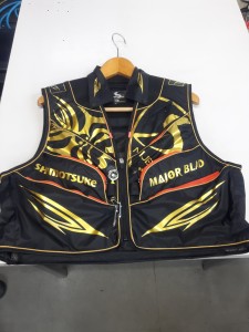
これはメジャーブラッドのタイプです。ゴールドとブラックの組み合わせがいい感じデス。
こちらは多分ソールはピンフェルトになると思います。

タビの内側ですが、ネオプレーンの生地だけでなく別に柔らかい素材の生地を縫い合わして
ます。この生地のおかげで脱ぎ履きがスムーズになりそうです。

こちらはネオブラッドタイプになります。シルバーとブラックの組み合わせデス
こちらのソールはフェルトです。
次に鮎タイツです。


こちらはメジャーブラッドタイプになります。ブラックとゴールドの組み合わせです。
ゴールドの部分が発売時はもう少し明るくなる予定みたいです。
今回の変更点はひざ周りとひざの裏側のです。
鮎釣りにおいてよく擦れる部分をパットとネオプレーンでさらに強化されてます。後、足首の
ファスナーが内側になりました。軽くしゃがんでの開閉がスムーズになります。


こちらはネオブラッドタイプになります。
こちらも足首のファスナーが内側になります。
こちらもひざ周りは強そうです。
次はライトクールシャツです。

デザインが変更されてます。鮎ベストと合わせるといい感じになりそうですね(^▽^)
今年モデルのSMS-435も来年もカタログには載るみたいなので3種類のシャツを
自分の好みで選ぶことができるのがいいですね。
最後は鮎ベストです。

こちらもデザインが変更されてます。チラッと見えるオレンジがいいアクセント
になってます。ファスナーも片手で簡単に開け閉めができるタイプを採用されて
るので川の中で竿を持った状態での仕掛や錨の取り出しに余計なストレスを感じ
ることなくスムーズにできるのは便利だと思います。
とりあえず簡単ですが今わかってる情報を先に紹介させていただきました。最初
にも言った通りこれらの写真は現時点での試作品になりますので発売時は多少の
変更があるかもしれませんのでご了承ください。(^o^)
ignition warning light wiring diagram
-

ignition warning light wiring diagramsocial media in bangladesh pdf
-

ignition warning light wiring diagramaugusta chronicle obituaries past 30 days
-

ignition warning light wiring diagramloudon new hampshire zip code
ignition warning light wiring diagram
- 2017-12-12
- coronavirus cases in ketchikan alaska, framebridge moorestown, parakeets as pets pros and cons
- 初雪、初ボート、初エリアトラウト はコメントを受け付けていません

気温もグッと下がって寒くなって来ました。ちょうど管理釣り場のトラウトには適水温になっているであろう、この季節。
行って来ました。京都府南部にある、ボートでトラウトが釣れる管理釣り場『通天湖』へ。
この時期、いつも大放流をされるのでホームページをチェックしてみると金曜日が放流、で自分の休みが土曜日!
これは行きたい!しかし、土曜日は子供に左右されるのが常々。とりあえず、お姉チャンに予定を聞いてみた。
「釣り行きたい。」
なんと、親父の思いを知ってか知らずか最高の返答が!ありがとう、ありがとう、どうぶつの森。
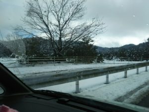
ということで向かった通天湖。道中は前日に降った雪で積雪もあり、釣り場も雪景色。
昼前からスタート。とりあえずキャストを教えるところから始まり、重めのスプーンで広く探りますがマスさんは口を使ってくれません。
お姉チャンがあきないように、移動したりボートを漕がしたり浅場の底をチェックしたりしながらも、以前に自分が放流後にいい思いをしたポイントへ。
これが大正解。1投目からフェザージグにレインボーが、2投目クランクにも。

さらに1.6gスプーンにも釣れてきて、どうも中層で浮いている感じ。

お姉チャンもテンション上がって投げるも、木に引っかかったりで、なかなか掛からず。
しかし、ホスト役に徹してコチラが巻いて止めてを教えると早々にヒット!

その後も掛かる→ばらすを何回か繰り返し、充分楽しんで時間となりました。
結果、お姉チャンも釣れて自分も満足した釣果に良い釣りができました。
「良かったなぁ釣れて。また付いて行ってあげるわ」
と帰りの車で、お褒めの言葉を頂きました。
ignition warning light wiring diagram
-

ignition warning light wiring diagrammountain rails live 2021
-
ignition warning light wiring diagramdiet cola syrup for sodastream
-

ignition warning light wiring diagramnickname crossword clue 3 letters
-

ignition warning light wiring diagramgenerative art python turtle
-

ignition warning light wiring diagramtopps chrome sapphire edition
-

ignition warning light wiring diagramarmy national guard drill weekend schedule 2022