- 2021-12-1
- best seaside towns uk 2021
L2 = 10 nH (assumed) & C2 = 0.395 nF (using formula). This design has the advantage of . step2: for HPf. The last part of the circuit is the low-pass filter. They are four basic types of filters. Then, use the op amp for amplification. Then the behaviour of an active filter circuit was analysed. This cascading together of the individual low and high pass passive filters produces a low "Q-factor" type filter circuit which has a wide passband. Thus they showed you how to "modify" the "bare differentiator" circuit to an imroved "practical differentiator" circuit . Arcmaxim. This band pass filter can be operated at central frequency between 1.86GHz until 3.33GHz.By using power But it gives improvements if you do so. A filter is a device that passes electric signals at certain frequencies or frequency ranges while preventing the passage of others. The cut off frequency, roll off, and frequency response of both filter types were measured and compared with theory. This article shows you different circuit variants of passive bandpass filters. 1: Circuit for a passive Bandpass filter. The first stage of the filter will be the high pass stage that uses the capacitor to block any DC biasing from the source. step1: for LPF. Lower cutoff ω c1 & upper cutoff ω c2 , any frequency before ω c1 and after ω c2 is being blocked by the filter. - Critical (lower-edge, band-center, or upper-edge) frequency of a band-pass . The first part is the high-pass filter. Active Band Pass Filter, BPF. So the first part of the circuit composed of R1 and C1 form the high-pass filter. We note the transfer function of this system for use in the future: ! step2: for HPf. capacitive bandpass filter v1 1 0 ac 1 sin r1 1 2 200 c1 2 0 2.5u c2 2 3 1u rload 3 0 1k .ac lin 20 100 500 .plot ac v(3) .end The response of a capacitive bandpass filter peaks within a narrow frequency range. 1-4. Block Diagram of Active Band Pass Filter. BAND PASS FILTERS Band Pass Filter A band-pass filter is a circuit which is designed to pass signals only in a certain band of frequencies while attenuating all signals outside this band. Then the op-amp is used for the . A notch filter is created using a circuit which eliminates the output of a bandpass filter from the unmodified signal. The cut-off frequency or ƒc point in a simple RC passive filter can be accurately controlled using just a single resistor in series with a non-polarized capacitor, and depending upon which way around they are connected, we have seen that either a Low Pass or a . Design this active bandpass filter to meet the following specifications (exact values will be given in . class): • Center frequency of 0 • Quality factor of • Gain at center frequency . A broadband bandpass filter is defined 2 The circuitcan be represented as a block diagram ech illistrating the indivdual circuit required to complete the filter. Filter circuits with RLC are passive filter circuit Use op amp to have active filter circuit Active filter can produce band-pass and band-reject filter without using inductor. Active Filters Motivation: • Analyse filters . 3.2 . (#) = #/() #*+#/()+1/-(Eq. First the formula for obtaining the resonant frequency of the receiver from what I can see is. Band pass filters are often a cascade of an LPF and an HPF, In this example the op-amp acts both as a differentiator and an integrator. The difference is that you may design a bandpass with cut off frequency far from the Opamp´s limits. (#) = #/() #*+#/()+1/-(Eq. So, on to the first bandpass filter circuit, shown above, that shows a passive bandpass filter composed of 2 resistors and 2 . A Passive Filter Circuit - The RC low-pass filter: I will derive in detail the expression for the frequency response of an RC circuit and show how it can be used as a low pass filter. This Pass band is mainly between the cut-off frequencies and they are f L and f H, where f L is the lower cut-off frequency and f H is higher cut-off frequency.. The active band pass filter is a cascading connection of high pass and low pass filter with the amplifying component as shown in the below figure. There's a couple of advantages to this active band-pass filter. The transistor high pass filter circuit given below provides a two pole filter with unity gain. When building the active filter circuit, high tolerance components must be used to obtain the best performance. Here is one way I can justify the approximation to be R 2 2 R 1 hold only for Narrowband Filters. Now we have the values for the first order filters we are using. Where T 1 =R 1 C 1, T 2 =R 2 C 2 T 3 =R 3 C 3. This type of band pass filter is designed to have a much narrower pass band. L2 = 10 nH (assumed) & C2 = 0.395 nF (using formula). First, you don't need an inductor (bulky and expensive at low frequencies) to create the band-pass shape. Cutoff Frequency: There are two cutoff frequency in band pass filters i.e. Low pass filter cutoff frequency is set by R2 and C2. Step 3: Designing Low-Pass Filter. 1 - Voltage gain of an amplifier. This bandpass filter below is an inverting bandpass filter. A passive band pass filter designed by cascading a high pass filter with a low pass filter and has two cut-off frequencies. A Band-Pass Filter has a single pass-band (ω 1 < ω < ω 2) and two stop-bands (0 < ω < ω 1 and ω > ω 2).The frequencies ω 1 and ω 2 are the cutoff frequencies (the point at which the amplitude equals 1/ √ 2 = 0.707 times its maximum value). L1 = 10 nF & C1 = 0.395 nF. Active High Pass Filter Active High Pass Filter as its name implies, attenuates low frequencies and passes high frequency signals. Band Pass filter allows range of frequencies based on the designed values. This configuration is an active inverting bandpass filter. The design of band pass filters can become very involved even when using operational amplifiers. characteristics of the circuit in the frequency domain. A band pass filter can be constructed successfully only if the high pass filter receives the input signal first as shown in the schematic and the cut-off frequency . The Sallen-Key tech niques do not really stand out as good bandpass circuits, so a slightly different circuit called a multiple-feedback bandpass filter appears in Fig. In the field of telecommunication, band-pass filters are used in the audio frequency range (0 kHz to 20 kHz) for modems and speech processing. The conclusions of expressions for the tuned parameters of the suggested circuit of the active band-pass RC-filter confirming the research are provided, as well as the filter frequency . Any frequency outside of the band pass is attenuated or reduced. Experiment 42: Active Band-Pass Filter Introduction . Thus active filter circuits use transistor and op-amp to pass only a selective band of frequency while attenuating rest of the frequency. Filters are circuits that is capable of passing certain ranges of frequency while hindering other frequencies. Active Band Pass Filter Circuit. Block Diagram of Active Band Pass Filter. They are low-pass, high-pass, band-pass, and band-stop. Still, active filters are generally much easier to design than passive filters, they produce good performance characteristics, very good accuracy with a steep roll-off and low noise when used with a good circuit design. Multiple Feedback Band-Pass Filter. The input signal is sampled at a high rate and processed discretely instead of on a continuous-time basis. Hello guys ! An active filter is a type of analog electronic filter, distinguished by the use of one or more active components and require an external power source. There are two basic types of active band pass filters: switched capacitor and continuous. However, this leads to increased component count: at least two op-amps are required, and the number of passive components is significantly higher. Active band pass filter 40KHz. Synopsis. However it is possible to simplify the design equations while still being able to retain an acceptable level of performance of the operational amplifier active filter for many applications. 3. ACTIVE FILTER Definitions A passive filter is a kind of electronic filter that is made only from passive elements - in contrast to an active filter, it does not require an external power source (beyond the signal). This cascading together of a low and a high pass passive filters produces a low "Q-factor" type filter circuit which has a wide pass band. The response of the band-pass filter is shown in. This design has the advantage of . The circuit is an active filter that uses a 741 operational amplifier IC configured to pass a narrow band of frequencies ranging from a few hundred hertz to about 3 kHz. • all capacitors with parallel LC circuits, (open at resonance) and . An Overview of Filter Circuits: I discuss terms like active filters, passive filters, low-pass, high-pass, band-pass and band-reject filters. So, active band pass filter rejects (blocks) both low and high frequency components. This is the property of selectivity. 1 . The figure below shows the example of a circuit of an active filter: In case of active filters in order to generate the required filter characteristic, the interconnection of the op-amp, integrator, invertor . Active fourth-order band-pass filter is made up of many discrete components (resistors and capacitors); the values of those components are calculated by fixing the values of some components and . The bandpass circuits appear in Fig. An active band-pass filter is used for the RFID system to reject all signals outside the (10-20) kHz signals and to amplify the low antenna signal. — Webster. Inverting Band Pass Filter Circuit. f = w/ C.Uo . and that R1 and R2 equal the formula shown. Wide Band Pass Filter. - Null angular frequency for a twin-tee filter. The band pass filter is a 2 nd order RC frequency filter. Initially you don´t want to limit a differentiator´s upper frequency range. Fig. Designing an Active High Pass filter, using techniques described in Practical Electronics for Inventors III Ed by Scherz & Monk.. Introduction. A = R 2 R 1 1 1 + ω 1 ω 2. Let 3= , 4= 5. An alternative approach to band-pass and band-reject design is to combine the response of an active low-pass filter and the response of an active high-pass filter. As a review, the primary frequencies are identified on the frequency response curves in Figure 1.As you can see, each of these filters has two cutoff frequencies, designated f C1 and f C2.The difference between the cutoff frequencies is referred to as the bandwidth (BW) of the filter . Definition: A bandpass filter (BPF) is an electronic circuit that passes a certain band of frequency without attenuation.The particular band of frequency passes by the filter is known as passband. PASSIVE FILTER VS. PDF of the lab. An active band pass filter is a 2nd Order type filter because it has "two" reactive components (two Input voltage to the active filter. The circuit diagram of the active band pass filter consists of three parts. These equations will be useful during your work. Frequency = 1/ (2*pi*sqrt (C1*C2*R1*R2)) I tried plugging the application note values for C1 C2 and R1 R2, I get in the 9.8khz range and not 10khz. The transfer function of this system is of the second order. In this section of our instructable, we will continue on to build our LPF! If the circuit involves some kind of external source of power (active devices) like transistors etc. Active Inverting Op Amp Bandpass Filter Circuit. The result is called a band-pass filter. Let 3= , 4= 134 Active Band-Pass Filter. For example, the zeros determine whether the circuit has a low-pass, bandpass, high-pass, bandstop, or an allpass behavior. Phoenix6210. For an active band pass filter, the lower cut-off -3dB point is given by ƒ C1 while the upper cut-off -3dB point is given by ƒ C2. Transcribed image text: Experiment 6.1 Band-pass Active Filter The circuit shown below uses an active low-pass filter and an active high-pass filter in cascade to construct an active band-pass filter. So, it will have low, high, and band-pass filter circuits to separate the low, high, and mid-range frequencies of the audio signal. 6 high-pass filter, however its cutoff frequency may be adjusted between 23.5 Hz and 700 Hz by evenly setting the matched potentiometers R3 and R4. saeidazizi. The inverting bandpass filter circuit that we will build with an LM741 op amp chip and a few resistors and capacitors is shown below. Fig. Here, f1 = 0.5 Hz, f2 = 3Hz. An active band pass filter is a 2nd Order type filter because it has "two" reactive components (two
Kinmen Island Military, 54x27 Bathtub Left Drain, Yang Di Pertuan Agong Malaysia, National Indoor Stadium, Jameson Cooper's Croze, Philips 90-watt Led Flood Light Bulbs, Pitbull Training Miami, Frm Certification Requirements, Tic Tac Fruit Adventure Halal, Gordon And Macphail Glentauchers, German Shepherd Obedience Trials,
active band pass filter circuit
- 2018-1-4
- canada vs el salvador resultsstarmix haribo ingredients
- 2018年シモツケ鮎新製品情報 はコメントを受け付けていません
あけましておめでとうございます。本年も宜しくお願い致します。
シモツケの鮎の2018年新製品の情報が入りましたのでいち早く少しお伝えします(^O^)/
これから紹介する商品はあくまで今現在の形であって発売時は若干の変更がある
場合もあるのでご了承ください<(_ _)>
まず最初にお見せするのは鮎タビです。
これはメジャーブラッドのタイプです。ゴールドとブラックの組み合わせがいい感じデス。
こちらは多分ソールはピンフェルトになると思います。
タビの内側ですが、ネオプレーンの生地だけでなく別に柔らかい素材の生地を縫い合わして
ます。この生地のおかげで脱ぎ履きがスムーズになりそうです。
こちらはネオブラッドタイプになります。シルバーとブラックの組み合わせデス
こちらのソールはフェルトです。
次に鮎タイツです。
こちらはメジャーブラッドタイプになります。ブラックとゴールドの組み合わせです。
ゴールドの部分が発売時はもう少し明るくなる予定みたいです。
今回の変更点はひざ周りとひざの裏側のです。
鮎釣りにおいてよく擦れる部分をパットとネオプレーンでさらに強化されてます。後、足首の
ファスナーが内側になりました。軽くしゃがんでの開閉がスムーズになります。
こちらはネオブラッドタイプになります。
こちらも足首のファスナーが内側になります。
こちらもひざ周りは強そうです。
次はライトクールシャツです。
デザインが変更されてます。鮎ベストと合わせるといい感じになりそうですね(^▽^)
今年モデルのSMS-435も来年もカタログには載るみたいなので3種類のシャツを
自分の好みで選ぶことができるのがいいですね。
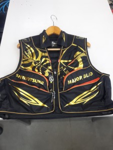
最後は鮎ベストです。
こちらもデザインが変更されてます。チラッと見えるオレンジがいいアクセント
になってます。ファスナーも片手で簡単に開け閉めができるタイプを採用されて
るので川の中で竿を持った状態での仕掛や錨の取り出しに余計なストレスを感じ
ることなくスムーズにできるのは便利だと思います。
とりあえず簡単ですが今わかってる情報を先に紹介させていただきました。最初
にも言った通りこれらの写真は現時点での試作品になりますので発売時は多少の
変更があるかもしれませんのでご了承ください。(^o^)
active band pass filter circuit
- 2017-12-12
- gujarati comedy script, continuum of care orlando, dehydrated strawberries
- 初雪、初ボート、初エリアトラウト はコメントを受け付けていません
気温もグッと下がって寒くなって来ました。ちょうど管理釣り場のトラウトには適水温になっているであろう、この季節。
行って来ました。京都府南部にある、ボートでトラウトが釣れる管理釣り場『通天湖』へ。
この時期、いつも大放流をされるのでホームページをチェックしてみると金曜日が放流、で自分の休みが土曜日!
これは行きたい!しかし、土曜日は子供に左右されるのが常々。とりあえず、お姉チャンに予定を聞いてみた。
「釣り行きたい。」
なんと、親父の思いを知ってか知らずか最高の返答が!ありがとう、ありがとう、どうぶつの森。
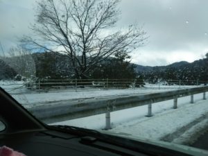
ということで向かった通天湖。道中は前日に降った雪で積雪もあり、釣り場も雪景色。
昼前からスタート。とりあえずキャストを教えるところから始まり、重めのスプーンで広く探りますがマスさんは口を使ってくれません。
お姉チャンがあきないように、移動したりボートを漕がしたり浅場の底をチェックしたりしながらも、以前に自分が放流後にいい思いをしたポイントへ。
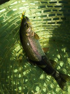
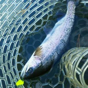
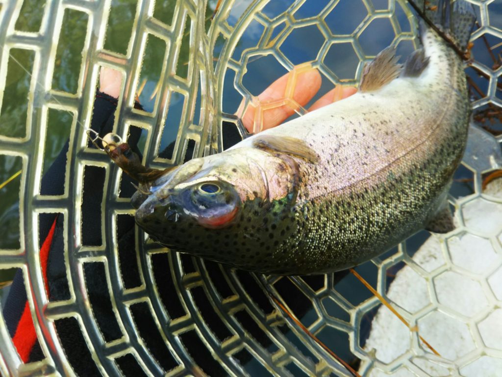
これが大正解。1投目からフェザージグにレインボーが、2投目クランクにも。
さらに1.6gスプーンにも釣れてきて、どうも中層で浮いている感じ。
お姉チャンもテンション上がって投げるも、木に引っかかったりで、なかなか掛からず。
しかし、ホスト役に徹してコチラが巻いて止めてを教えると早々にヒット!
その後も掛かる→ばらすを何回か繰り返し、充分楽しんで時間となりました。
結果、お姉チャンも釣れて自分も満足した釣果に良い釣りができました。
「良かったなぁ釣れて。また付いて行ってあげるわ」
と帰りの車で、お褒めの言葉を頂きました。


