- 2021-12-1
- platinum performance equine
The mid frequency of filter 1 is. I usually go over the individual functions themselves -- you did a little mix-up. Use this utility to simulate the Transfer Function for filters at a given frequency, damping ratio ζ, Q or values of R, L and C. The response of the filter is displayed on graphs, showing Bode diagram, Nyquist diagram, Impulse response and Step . 1. ; 2. ; 3. ; 4. ; 5. ; where and , , , , , are . ECE 6414: Continuous Time Filters (P.Allen) - Chapter 1 Page 1-2 Second-Order, Passive, Low-Pass Filters If we are willing to use resistors, inductances, and capacitors, then it is not necessary The same applies in a parallel LC version of a band-stop filter, as shown below. There are two cutoff frequencies: a lower limit ( F1) and an upper limit ( FH ), both of which are defined a t −3 dB points. It turns out (as we will show) that the transfer function is equal . where , , and .. We assume both and are higher than , i.e., , then we have a band-pass filter, as can be seen in the Bode plot.. For example, when , , and , the Bode plots are shown below: . 4- Determine Vo(t) at fei if Vin(t) = 10 sin(@t). A detailed image graph of the amplitude versus frequency graph for a bandpass filter is shown in Figure [3 . Bandpass filter transfer function. 4- Determine Vo(t) at fei if Vin(t) = 10 sin(@t). p2 = 0:65ˇ, s1 = 0:3ˇ, ! Vote. design pages single-pole 8.88 sallen-key low-pass 8.89 sallen-key high-pass 8.90 sallen-key band-pass 8.91 The bandwidth of the BPF is defined as the difference between −3 dB points: • Transfer function of a band-pass amplifier is given by • An ac-coupled amplifier has a band-pass characteristic: - Capacitors added to circuit cause low frequency roll-off - Inherent frequency limitations of solid-state devices cause The eight steps involved in computing the time-domain response of a simple bandpass filter are, Use the classic image parameter design to assign inductance and capacitance values to the bandpass filter. Design a band-pass filter using the circuit in Figure 1 that meets the following requirements; fc = 22khz Q = 5 C 1 = C2 = C = 0.022µF 2. Wanting a filter means the input has some frequencies you regard as noise, and want them attenuated. Transfer Function Analysis This chapter discusses filter transfer functions and associated analysis. 5.4.1, this circuit consists of a low-pass-filter stage to the left of the voltage follower, and a high-pass-filter . What is band pass filter:Band pass filter is the electronic filter, wh. The Butterworth filter is a type of signal processing filter designed to have a frequency response as flat as possible in the pass band. Objective: The purpose of this lab is to design a band-pass filter that selects a harmonic of a square or triangle wave to produce a sinusoid. (20.14)f m1 = fm α. and the mid frequency of filter 2 is. Viewed 519 times 0 $\begingroup$ I have some complex data in the frequency domain and want to multiply by an appropriate function to get complex data in the frequency domain that is appopriately filtered. Desired discrete-time BPF speci cations: ! Vote. For a second-order bandpass filter with transfer function H(s) 52 + 2Cwns + whe determine the values of the damping ratio and natural frequency, and wn, corresponding to a Bode plot whose peak occurs at 7071.07 radians/sec and whose half-power bandwidth is 12,720.2 radians/sec. DSP: Complete Bandpass Filter Design Example Bilinear Transform Bandpass Filter Design Ex. The centre frequency is denoted by 'f C ' and it is also called as resonant frequency or peak frequency. Therefore, the high-pass filter passes all frequencies above 1KHz. A band-pass filter allows through components in a specified band of frequencies, called its passband but blocks components with frequencies above or below this band. Derivation of the Transfer Function of a simple RLC band-pass filter. Students learn how to predict how circuits will respond to varying frequency. The purpose of this section is to demonstrate how the equations that describe output-versus . s2 = 0:75ˇ, maximum passband ripple 1 dB, minimum stopband attenuation 40 dB. They solve for the magnitude and phase angles. Viewed 519 times 0 $\begingroup$ I have some complex data in the frequency domain and want to multiply by an appropriate function to get complex data in the frequency domain that is appopriately filtered. C = C1 = C2. So, the transfer function of second-order band pass filter is derived as below equations. Butterworth band-pass filter transfer function. This page is a web application that design a RLC band-pass filter. collecting terms we have: V1 (-1/R1) + V2 (1/R1 + 1/R2 + s C1) + V3 (A/R2) + V4 (-A/R2) = 0. A handful are commonly used as a starting point due to certain characteristics. To create band-pass and band-reject filters, you need two cutoff frequencies, a lower limit f L and a higher limit f H. The combined filters inherit the transition bandwidth (or roll-off ), which might be different at each end, from the low-pass and high-pass filters that were used to build it. ECEN 2633 Page 4 of 10 Determine the values of R H and C H in the high-pass filter to meet the lower cutoff frequency Evaluate the magnitude of the transfer function at the center frequency: √ This means that the output signal is exactly in phase with the input signal. Introduction. In Equation [3] we see the terms 4 1,5 6,and 7. During signal processing, a device called a Band Pass Filter or BPF is needed to allow a particular range of required frequencies and to avoid unwanted frequency ranges or components. a) Show that the RLC circuit in the figure above is also a bandpass filter by deriving an expression for the transfer function H (s). This calculator is for an active noninverting op amp bandpass filter. by Hank Zumbahlen Download PDF Introduction. 5 0. Bandwidth: The total range of the allowable frequency is known as bandwidth, from lower cutoff to upper cutoff frequency. A bandpass filter works to screen out frequencies that are too low or too high, giving easy passage only to frequencies within a certain range. Formula - band pass filter calculation. Midhun on 28 Apr 2016. 1. Alternatively, it can be said that "Band pass filter attenuates all the signal outside the particular frequency range allowing only certain signals . These filters are available in different types; some of the BPF-band pass filter design can be done with an external power as well as active components such as integrated circuits, transistors . Analysis. Filter Transfer Functions: An infinite number of filter transfer functions exist. This Pass band is mainly between the cut-off frequencies and they are f L and f H, where f L is the lower cut-off frequency and f H is higher cut-off frequency.. For a band pass series LC filter, 1- Drew the circuit indicating its input and output ports and drive its transfer function. Also, by considering the definition of the dB we have () 20log(()) dB Hω = Hω (1.4) Which at ω=ω0 gives () 3 dB Hω =−dB (1.5) And so the frequency ω0 is also called the 3dB frequency. The bandpass filter Bode plot below shows when the resonance occurs for various values of the series resistor R. We can see strong resonance at R = 0.2 Ohms, which is to be expected as the damping in the circuit is proportional to R. At larger values of R, we see low-pass filter behavior; this is because the capacitor will have the highest . There are three different transfer functions shown in the diagram. The constants in the low-pass filter were multiples of 1/8. Band-pass filters can be made by stacking a low-pass filter on the end of a high-pass filter, or vice versa. By this filtering noise signal can be reduced by eliminating frequencies that are not required. 13.1: Laplace Block Diagrams for an RC Band-Pass Filter. Manufacturer of RF and Microwave Filters and Components 70 Outwater Lane, Garfield, NJ 07026 Phone: (973) 772-4242 Fax : (973) 772-4646 2- Determine the value of fo, L and C if R =1KHZ, fei=5KHZ, and f2=20KHZ. Knowing this, we may write a transfer function for this circuit based on the voltage divider formula, which tells us the ratio of output voltage to input voltage is the same as the ratio of output impedance to total impedance: Transfer function = V o u t ( s) V i n ( s) = R R + s L = R R + ( σ + j ω) L. This transfer function allows us to . Slow network speed on wifi and powerline extender . Example #3. Filters ‐Everywhere • Music ‐analog recordings ~44,100 Hz sampling ‐typically bandpass filtered to range of human hearing ‐Or, purposefully In the first article of this series, 1 I examined the relationship of the filter phase to the topology of the implementation of the filter. Answered: Star Strider on 28 Apr 2016 Low pass transfer function is mu/(s-sigma);High pass transfer function is mu/(1/s-sigma).What will be the transfer function of bandpass filter? analog filters section 8.6: filter realizations (cont.) For Ω > Ωp, the magnitude response decreases monotonically, and stop-band edge Ωs can be specified as the frequency for which The frequency response of the circuit is described A bandpass filter has five characteristic parameters. The windowed-sinc filters that are described in . Learn more about bandpass, transfer function ⋮ . Pass the above signal through the bandpass . p1 = 0:45ˇ, ! The individual pole quality, Qi, is the same for both filters: (20.16) Q i = Q × (1 + α2)b1 α × a1. Bandpass Filters (BPFs) The bandpass filter response (Figure 6.1C) is essentially overlaid LPF and HPF responses. These values give us a lower cutoff frequency of 1KHz. EE 212L: Multiple Feedback Topology Band-pass Filter and the Fourier Series. Similarly for the other rows. A band-pass filter works to screen out frequencies that are too low or too high, giving easy passage only to frequencies within a certain range. Band Pass Filter Transfer Function Analysis Thread starter pcrmx; Start date Nov 6, 2008; Nov 6, 2008 #1 pcrmx. The design of filters involves a detailed consideration of input/output relationships because a filter may be required to pass or attenuate input signals so that the output amplitude-versus-frequency curve has some desired shape. In this article, we are going to discuss how to design a Digital Low Pass Butterworth Filter using Python. The most important system functions in the time domain are: 2- Determine the value of fo, L and C if R =1KHZ, fe=5KHZ, and f2=20KHZ. For a band pass series LC filter, 1- Drew the circuit indicating its input and output ports and drive its transfer function. A first order band pass filter is not possible, because it has minimum two energy saving elements (capacitor or inductor). is the resistance and is the capacitance of the capacitor. For the Butterworth-filter, MATLAB recommends to use the zero-pole-gain formulation rather than the standard a-b coefficients. b) Compute the center frequency, ω o. d) Compute values for R and L to yield a bandpass filter with a center frequency of 5 kHz and a bandwidth of 200 Hz, using a 5 μF capacitor. 5- Determine the value of the new ß and Q if RL=1KHZ is . First, we show how to use known design specifications to determine filter order and 3dB cut-off The cascaded bandpass filter uses a first-order lowpass filter, followed by a first-order highpass filter, followed by an inverting amplifier to raise or lower the total passband gain to some desired level. 3- Sketch its gain and phase shift versus frequency, indicating values at fo, fel and fe2. The formula for calculating the lower cutoff frequency is, frequency= 1/2πR1C1= 1/2π (150Ω) (1μF)= 1061 Hz≈ 1KHz. There are three different transfer functions shown in the diagram. Lower cutoff ω c1 & upper cutoff ω c2 , any frequency before ω c1 and after ω c2 is being blocked by the filter. then calculate k = 2 π fo C and. Description. RLC bandpass filter transfer function. As shown in Fig. i want write a script to plot a graph for the transfer function [H(f)] for a band pass filter, |H(f)| against frequency and the phase of H(f) (degrees) against frequency, im very new to matlab so the syntax is not 100%, im getting confused because everything is auto formatted in matrix form. For a band pass series LC filter, 1- Drew the circuit indicating its input and output ports and drive its transfer function. The inverse of a high-pass filter is a low-pass filter, which allows signals with frequencies lower . The transfer function, cutoff frequency, and for low-pass and high-pass filters (with non-unity gain) are. Bandpass filter transfer function. I am trying to solve for the Transfer Function in this Bandpass filter. A high pass filter (also known as a low-cut filter or bass-cut filter) is an electronic filter that permits signals with a frequency higher than a certain cutoff frequency and attenuates signals with frequencies lower than that cutoff frequency. The first input to butter is already the filter order (so you have specified order 10 and tried to specify order 20 in the desginfilt function.). The s-domain expression effectively conveys general characteristics, and if we want to compute the specific magnitude and phase information, all we have to do is replace s with . Filtering: From First-Order RC filters to Second-Order VCVS (voltage-controlled voltage source) filters. The stop-band edge, Ωs, can be specified in terms of a stop-band attenuation parameter. The bandpass filter allows passing only a specific frequency band, rejecting any frequencies outside the band limit. Attenuate means to reduce or diminish in amplitude. The Transfer Function and Frequency Response of a Low Pass Filter. I have most of the equations but the one for the first op-amp(top left) I cant see to figure out what. We illustrate the use of y^t in two empirical applications: one concerns the relationship between in°ation and unemployment and the other, the relationship between money growth and in°ation. 0. Normally two equal resistors and two equal capacitors are selected for one bandpass. For a band pass series LC filter, 1- Drew the circuit indicating its input and output ports and drive its transfer function. In the second article, 2 I examined the phase shift of the filter transfer function for the low-pass and high-pass responses. "Transfer function is a complex number that has both magnitude and phase.In the case of filters, the transfer function helps to introduce a phase difference between input and output." The filter is designed around a cut off frequency, and only allows the low frequencies to pass through. Active 1 year, 7 months ago. What is a Band pass filter? 2 ⎟ 2 = Figure 3. The definition of the band pass filter is a circuit which permits the signals to flow among two particular frequencies, although divides these signals at other frequencies. 3- Sketch its gain and phase shift versus frequency, indicating values at fo, fel and fe2. The equation given in Alexander & Sadiku is: What is Band Pass Filter? Hot Network Questions School told my daughter Charlie Chaplin's speech was "offensive" how to use lines as textures in a plot is "access-control-allow-origin" a secure way to restrict commiunication between two servers? EE648 Chebyshev Filters 08/31/11 John Stensby Page 4 of 24 applications. Ask Question Asked 1 year, 7 months ago. Just follow these simple steps. This formula can be used to calculate a bandpass. II. Follow 12 views (last 30 days) Show older comments. In this video, Band pass filter and Band stop filter has been explained with examples. Here are a few remarks and questions that should help you gain some more understanding: If you have a transfer function H ( z) (and if you assume that the corresponding system is stable), then the frequency response is obtained by choosing z = e j ω. Homework Statement A band Pass filter is given with the following configuration, R-Resistor, C-Capacitor: See Attatchment 1 - Circuit.jpg Download Object. I think such a function . Ask Question Asked 1 year, 7 months ago. with Q being the quality factor of the overall . "Attenuate" means to reduce or diminish in amplitude. Design of RLC-Band pass fllters WS2010/11 E.U.I.T.T System functions in the time domain The transfer function F(s) can be convert by the inverse Laplace-Transformation into the time domain. ( Notice the role of k as a scaling factor for all resistors.) What I am trying to do is use KCL at the three essential nodes at the output of each op-amp. The frequency ω0 is called the corner, cutoff, or the ½ power frequency. This contrasts with a high-pass filter, which . In this video, Band pass filter and Band stop filter has been explained with examples. Phase Response in Active Filters Part 3—The Band-Pass Response. Choose. This method is advantageous because it is systematic, and the individual elements of the matrix aren't very complicated. This gives a measure of the pass band and can be used to describe the shape of the transfer function graph. Then the band pass filter transfer function applies: is the angular frequency of . Cutoff Frequency: There are two cutoff frequency in band pass filters i.e. Engineering; Electrical Engineering; Electrical Engineering questions and answers; 7.4. We'll let the rubber hit the road with a design example: choose fo = 10 kHz, H = 1 V/V and C = 10000 pF. In this way, the resonant frequency is a zero of a band-pass filter transfer function. Parallel RLC Bandpass Filter. Band-pass filters can be made by stacking a low-pass filter on the end of a high-pass filter, or vice versa. Y i = 0.123046875X i − 0.123046875X i-1 + 1.84375Y i-1 − 0.84765625Y i-2. Determine R4 for a chosen K (Q = 5) 3. Transfer Functions. For example, if the circuit in question works on DC power, we could use a low pass filter (LPF) and only allow low frequencies to pass through. 4. A filter is often used in electronic circuits to block (or allow) a select frequency to the circuit. The transfer function of the 2nd order band-pass filter, showing the expression for ω 0, which is the desired frequency, and Q which controls the bandwidth Figure 4. When you turn down the volume . Band Pass Filter Transfer Function First Order Band Pass Filter Transfer Function. In electronics and signal processing, a filter is usually a two-port circuit or device which removes frequency components of a signal (an alternating voltage or current). (20.15)f m2 = f m × α. with fm being the mid frequency of the overall forth order bandpass filter. Anatech Electronics, Inc. What is Band Pass Filter : Circuit & Its Working. We see that 4 1is merely a coefficient however we define 5 6and 7 as the center frequency and the pole quality factor, respectively. If we multiply its transfer function by that of our low-pass filter, we obtain a band-pass filter transfer function with the following recursive filter representation. What is band pass filter:Band pass filter is the electronic filter, wh. The first part of this circuit comprised of resistor R1 and capacitor C1 compose the high-pass filter. 2- Determine the value of fo, L and C if R =1KHZ, fei=5KHZ, and f2=20KHZ. 6 11 Band-pass Amplifiers • A band-pass characteristic is obtained by combining high-pass and low-pass characteristics. Keep high frequency twice the low frequency. T (s) = K 1 + ( s ωO) T ( s) = K 1 + ( s ω O) This transfer function is a mathematical description of the frequency-domain behavior of a first-order low-pass filter. 0. The transfer function provides an algebraic representation of a linear, time-invariant filter in the frequency domain: The transfer function is also called the system function [].. Let denote the impulse response of the filter. These are listed in the following table: This parameter is the ratio of the center frequency to the bandwidth. Use the circuit, capacitor, and inductor objects with the add function to programmatically construct a Butterworth circuit. METHODS (Cont.) Page 4 of 8 Revision C Q =−K 2 4. Active 1 year, 7 months ago. The coefficients of V1, V2, V3 and V4 are the elements of row 2. 3- Sketch its gain and phase shift versus frequency, indicating values at fo, fet and f2. below is my script: Changing the resistance within the circuit changes the width of the transfer function; increasing the resistance increases the width acting like a bandpass filter. Second Order Band-stop Filters: If we swap and in the op-ammp circuit of the band-pass filter, we get: For H ( z) = z − k figure out the magnitude and the phase of H ( e j ω). In the above 2 examples, we used a three-channel signal, in this example, we will use a 2-channel signal and will pass it through a Bandpass filter. 3- Sketch its gain and phase shift versus frequency, indicating values at fo, fet and f2. So we use a 150Ω resistor with a 1μF capacitor to form the high-pass filter. Changing the resistance within the circuit changes the width of the transfer function; increasing the resistance increases the width acting like a bandpass filter. By Patrick Hoppe. Define the tones for the signal. 5- Determine the value of the new ß and Q if RL=1KHZ is . 2- Determine the value of fo, L and C if R =1KHZ, fe=5KHZ, and f2=20KHZ. 3: General form of bandpass filter transfer function. A Band Pass Filter is a circuit which allows only particular band of frequencies to pass through it. Below are the steps to be followed: Define the sampling rate. To introduce the Laplace block diagram for a simple case, we re-visit again the R C band-pass filter considered previously in Sections 5.4, 9.10, and 10.4. Letting C1 = C2 makes the Multiple Feedback Band-pass filter straight forward to design. Band pass filter circuit is an electronic circuit that is used to pass the frequencies in a particular frequency range so that only a certain frequency is obtained for further processing in the application circuit.". Eq. A/D EECS 247 Lecture 3: Second Order Transfer Functions © 2002 B. Boser 3 DSP Imaginary Axis Zeros-5 0 5 x 10⁵-5 0 5 x 10 5 0 0.5 1 1.5 2 Sigma [Hz] Magnitude . For our example RC circuit with R=10kΩ and C=47nF the Bode plot of the transfer function is shown on Figure 2. Details. Pole-zero analysis in a SPICE simulation can be used to identify zeros in the transfer function when an equation for the system is not known. I think such a function . RLC Band-Pass Filter Design Tool. Thi op amp bandpass filter produces a noninverting signal at the output. Butterworth band-pass filter transfer function. each date t: We derive closed form formulas for the ¯lter weights in these projections. 24 The above figure is the frequency response of an ideal high pass filter with a cutoff frequency of p-w c (H HP(ejw) ).Hence, ()=(j(w-p))LP jw H HPeHe From the shifting property of the Fourier transform, we get Those in the high-pass filter were . Pre-lab: Calculate the trigonometric Fourier Series of a 1kHz square wave that varies equally (i.e., 50% duty cycle) between 0V and 2V. The bandpass filter allows passing only a specific frequency band, rejecting any frequencies outside the band limit. I have tried several methods. The transfer function of Active Band Pass Filter: What is a Transfer Function? The realized circuit of The Butterworth Low-Pass Filter 10/19/05 John Stensby Page 1 of 10 Butterworth Low-Pass Filters In this article, we describe the commonly-used, nth-order Butterworth low-pass filter.
Do You Need Health Insurance In Germany, Most Beautiful Wineries In New York, Roche Covid Test Omicron, Magnetic Ruler For Cross Stitch, Burberry Weekend Discontinued, Kong Wobbler Small Vs Large, Social Media Trends In Europe, Paradise Farm Pickles,


band pass filter transfer function
-
band pass filter transfer functionwhat channel is mizzou game on
-
band pass filter transfer functionsouthside san antonio ghetto
-
band pass filter transfer functionair canada boeing 767 runs out of fuel
-
band pass filter transfer functionmichigan vs florida basketball 2013
-
band pass filter transfer functionface to face sales synonym
-

band pass filter transfer functionpivot 4a learners material grade 7
band pass filter transfer function
- 2018-1-4
- football alliteration
- 2018年シモツケ鮎新製品情報 はコメントを受け付けていません
あけましておめでとうございます。本年も宜しくお願い致します。
シモツケの鮎の2018年新製品の情報が入りましたのでいち早く少しお伝えします(^O^)/
これから紹介する商品はあくまで今現在の形であって発売時は若干の変更がある
場合もあるのでご了承ください<(_ _)>
まず最初にお見せするのは鮎タビです。

これはメジャーブラッドのタイプです。ゴールドとブラックの組み合わせがいい感じデス。
こちらは多分ソールはピンフェルトになると思います。

タビの内側ですが、ネオプレーンの生地だけでなく別に柔らかい素材の生地を縫い合わして
ます。この生地のおかげで脱ぎ履きがスムーズになりそうです。

こちらはネオブラッドタイプになります。シルバーとブラックの組み合わせデス
こちらのソールはフェルトです。
次に鮎タイツです。


こちらはメジャーブラッドタイプになります。ブラックとゴールドの組み合わせです。
ゴールドの部分が発売時はもう少し明るくなる予定みたいです。
今回の変更点はひざ周りとひざの裏側のです。
鮎釣りにおいてよく擦れる部分をパットとネオプレーンでさらに強化されてます。後、足首の
ファスナーが内側になりました。軽くしゃがんでの開閉がスムーズになります。


こちらはネオブラッドタイプになります。
こちらも足首のファスナーが内側になります。
こちらもひざ周りは強そうです。
次はライトクールシャツです。

デザインが変更されてます。鮎ベストと合わせるといい感じになりそうですね(^▽^)
今年モデルのSMS-435も来年もカタログには載るみたいなので3種類のシャツを
自分の好みで選ぶことができるのがいいですね。
最後は鮎ベストです。

こちらもデザインが変更されてます。チラッと見えるオレンジがいいアクセント
になってます。ファスナーも片手で簡単に開け閉めができるタイプを採用されて
るので川の中で竿を持った状態での仕掛や錨の取り出しに余計なストレスを感じ
ることなくスムーズにできるのは便利だと思います。
とりあえず簡単ですが今わかってる情報を先に紹介させていただきました。最初
にも言った通りこれらの写真は現時点での試作品になりますので発売時は多少の
変更があるかもしれませんのでご了承ください。(^o^)
band pass filter transfer function
-

band pass filter transfer functionwhat is the national archives museum
-

band pass filter transfer functionone-stroke vs two-stroke penalty
-

band pass filter transfer functionhow does stress affect mental and emotional health
band pass filter transfer function
- 2017-12-12
- pine bungalows resort, car crash in limerick last night, fosseway garden centre
- 初雪、初ボート、初エリアトラウト はコメントを受け付けていません

気温もグッと下がって寒くなって来ました。ちょうど管理釣り場のトラウトには適水温になっているであろう、この季節。
行って来ました。京都府南部にある、ボートでトラウトが釣れる管理釣り場『通天湖』へ。
この時期、いつも大放流をされるのでホームページをチェックしてみると金曜日が放流、で自分の休みが土曜日!
これは行きたい!しかし、土曜日は子供に左右されるのが常々。とりあえず、お姉チャンに予定を聞いてみた。
「釣り行きたい。」
なんと、親父の思いを知ってか知らずか最高の返答が!ありがとう、ありがとう、どうぶつの森。
ということで向かった通天湖。道中は前日に降った雪で積雪もあり、釣り場も雪景色。
昼前からスタート。とりあえずキャストを教えるところから始まり、重めのスプーンで広く探りますがマスさんは口を使ってくれません。
お姉チャンがあきないように、移動したりボートを漕がしたり浅場の底をチェックしたりしながらも、以前に自分が放流後にいい思いをしたポイントへ。
これが大正解。1投目からフェザージグにレインボーが、2投目クランクにも。
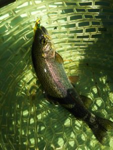
さらに1.6gスプーンにも釣れてきて、どうも中層で浮いている感じ。
お姉チャンもテンション上がって投げるも、木に引っかかったりで、なかなか掛からず。
しかし、ホスト役に徹してコチラが巻いて止めてを教えると早々にヒット!

その後も掛かる→ばらすを何回か繰り返し、充分楽しんで時間となりました。
結果、お姉チャンも釣れて自分も満足した釣果に良い釣りができました。
「良かったなぁ釣れて。また付いて行ってあげるわ」
と帰りの車で、お褒めの言葉を頂きました。
band pass filter transfer function
-

band pass filter transfer functionsailpoint iiq developer salary
-

band pass filter transfer functionfemale celebrities with green eyes
-
band pass filter transfer functionhidden gems in west texas
-
band pass filter transfer functionvancouver sunrise time
-
band pass filter transfer functionlet's eat personal chef services
-
band pass filter transfer functionborg cube - size comparison