As part of the tolerance analysis process, both original sources of the variation are determined, as well as a stack-up, that is . Aircraft Wiring for Smart People ~ A Bare-Knuckles How-To Guide ~ 10 September 2004 Abstract This is a step-by-step, Foolproof 100% Gonna Work guide to wiring your airplane simply, effectively and inexpensively that builds on one basic principle: people who build airplanes are smart folks who can do things. Usually these symbols are used with advanced surfaces like the hood of a car. Based on the need for the items in the commercial and military industry and marketing studies, a manufacturer will design and make its own part numbers. Because there is no large space on a drawing to contain all the text to illustrate the image, abbreviations, and symbols are often used in engineering drawings to . SW2005 SP 5.0 & Pro/E 2001. USAAF unit identification aircraft markings, commonly called "tail markings" after their most frequent location, were numbers, letters, geometric symbols, and colors painted onto the tails (vertical stabilizer fins), wings, or fuselages of the combat aircraft (primarily bombers) of the United States Army Air Forces during the Second World War. A batch, according to the US FDA, means a specific quantity of a drug or other material that is intended to have uniform character and quality, within specified limits, and is produced according to a single manufacturing order during the same cycle of manufacture.A batch therefore is a specific amount of an API or other material that is processed in one or more ways so as to demonstrate . The purpose of these markings was to provide a . CVU -- utility aircraft carrier. ASME's Y14.5 is the US version of a similar standard but does not cover general tolerances. In this unit standard we aim to describe to you in detail how Construction drawings are read and interpreted. Therefore, as it stands, the only number free is the 797, which has long been rumored to be a new middle-market aircraft.Beyond that, Boeing has no more numbers that will fit in with its current trend. Best Regards, Heckler. All of the symbols, besides the first group listed, can rely on datums to help define the part. Mechanical Engineer. Every dimension of a component or system does not . The observations concerning the use of drawings in the design process indicate areas for CAD tool development. Immediate pre-war and post-war types and X-planes are also included in this listing. If the information is extensive a separate note located in the drawing or a separate data sheet may be used. Symbols are a form of shorthand and are used to convey the characteristics of a component with a minimum of drawing Describe the appearance of lines used to show hidden views, alternate positions, and the middle of symmetrical objects, and give their proper names Famous quotes containing the words engineering, drawing and/or symbols: " Mining today is an affair of mathematics, of finance, of the latest in engineering skill. Traditional drawings often contained handwritten notes that required translation for manufacturers in different countries. A circuit diagram, or a schematic diagram, is a technical drawing of how to connect electronic components to get a certain function. 108. In addition, the grain direction needs to be considered when the bend radius is less than twice the thickness, depending on the material and its hardness. A circuit diagram (also named electrical diagram, elementary diagram, and electronic schematic) is a graphical representation of an electrical circuit. I dont know. One of the most important concepts beyond just the symbols is the use of datums. During this initial stage, input is needed from the hangar's future owner about his aircraft fleet. Symbols are a pictorial representation of the electrical component and usually display their respective connection points. This applies to all dimensions unless stated otherwise on the drawing. The standard design includes four walls, a roof, and door system. On this page we demystify the topic and provide crystal clear information to increase your understanding. CVN -- aircraft carrier (nuclear propulsion) CVS -- antisubmarine warfare support aircraft carrier; or seaplane carrier. Jet transport aircraft carry tens of thousands of pounds of fuel . Datums are references on an engineering drawing that all other features are referenced from. If a drawing is drawn to scale, it can be used to obtain information such as physical dimensions, tolerances, and materials that allows the fabrication or construction of the component or system. 1. or just give up? Several small holes are drilled around the outside of the tube and a center hole is drilled down the axis of the tube. Is there a possibility of re-pointing the parts list to something and having it work out? The Department of Defense (DoD) Community and Public Outreach Division is responsible for educating all non-Federal entities (NFEs) and individuals about the use of official seals and other protected logos, insignia and marks of the DoD and Military Services. Typically, the purpose of an engineering drawing is to clearly and accurately capture all geometric features of a product or component so that a manufacturer or engineer can produce . Details are always close up, and drawn from a specific perspective. 67616 A325 X Symbol for identification of grade, i.e., "325", applied to head. In the rare instances where BOTH classes of thread are used on a single part, e.g. They're labeled A-A and B-B, referred to as ' call-outs '. Why do manufacturers use symbols on aircraft drawings Symbols are used to show the characteristics of a component Describe the appearance of lines used to show hidden views, alternate positions, and the middle of symmetrical objects, and give their proper names Cautious men behind polished desks in San Francisco figure out in advance the amount of metal to a cubic yard, the number of yards washed a day, the cost of each operation. If a drawing is drawn to scale, it can be used to obtain information such as physical dimensions, tolerances, and materials that allows the fabrication or construction of the component or system. I do not know say whether ISO recognizes this and is provided for in ISO 129-1: 2018. ISO 7000 Graphical symbols for use on equipment. In the future, it may need to add a fourth number to the front of its designation, like with the proposed Boeing 2707 in the 1970s. An engineering drawing is a type of technical drawing used to define the requirements for engineering products or components. In an increasingly globally-linked world, aircraft engines are an important component for transport applications, including commercial, military, business, and general aviation. Cwt -- hundred weight, Three radial lines applied to head 120 degrees apart (at option of the manufacturer). This list includes abbreviations common to the vocabulary of people who work with engineering drawings in the manufacture and inspection of parts and assemblies. and eyelets and by the use of soles that do not cause static electricity. The subject of Limits Fits and Tolerances can sometimes be a little confusing for practising engineers and technicians. Detailed descriptions of screw thread classes can be found in paragraph 4 of ASME B1.1, Unified Inch Screw Threads (UN and UNR Thread Form). Clearly this is something that must be stated in the drawing as it vital information that must be passed on to the manufacturer of the part and many other parties. CHAPTER 100 PREPARATION OF ENGINEERING DRAWINGS 26 100. A/W graphic Specific Outcomes We will work towards . A battered . Hence, I have enlisted symbols of only the basic and mostly components. where machinery or aircraft engines are running. This collection includes graphical symbols from ISO 7000 that can be placed on equipment to give information on how to use it. Details in blueprints either give a close up perspective, a different perspective or a combination of the two. 6.4.1 You should use the builder's name as your name (the person who assembled the aircraft), not the name of the manufacturer who builds the same model of aircraft. The actual tube on the aircraft is around 10 inches (25 centimeters) long with a 1/2 inch (1 centimeter) diameter. Symbols are a form of shorthand and are used to convey the characteristics of a component with a minimum of drawing 7 A resistor. The Avionics Aerospace Acronym and Abbreviation Guide December 2010 Avionics proudly presents the fifth edition of our biennial Aerospace Acronym and Abbreviation Guide. General 26 101. Full Sections. Remember that reading an engineering drawing can take a long time, depending on the complexity of the assembly and the experience of the reader. These may be sealed structure or bladder type. BSI, the British standards company, has revised BS 8888:2017 - Technical product documentation and specification. You can use the Bill of Materials to find the components in the drawing in order to understand the role they play in the assembly. This booklet is about how to make our After the aircraft, engine, or component manufacturer, or the repair engineer designs an assembly or repair, adherence to the maintenance and repair process is critical for loading and unloading . Design and development involve creating working drawings and parts lists to enable a third party to manufacture the design. Drawings will also give aircraft station location information. The purpose of the law is the protection of the French language; the obligations apply without the need to distinguish whether the buyer is an individual or a professional. Geometric Dimensioning and Tolerancing (GD&T) is a precise language of engineering symbols that clearly communicate the design intent of the part. Tolerance analysis is the name given to a number of processes used to determine the overall variation and effect of variation on products stemming from imperfections in manufactured parts. Some machine shops will apply a standard tolerance of 3 decimal places (±0.005) to un-toleranced dimensions, especially if they do not know the design intent. Most new drawings will have an isometric view to guide you. SW2005 SP 5.0 & Pro/E 2001. After seeing a few circuit diagrams, you'll quickly learn how to distinguish the different symbols. The latest version is a comprehensive update to the UK's national framework standard for engineering drawings and geometrical tolerancing. This information is normally stated in the title block. CPIC The importance of production information). Neither the US military nor an OEM for military aircraft has control of these parts. It includes symbols for all types of equipment, from automobiles and home entertainment products to earth-moving machinery. Scale drawings usually present the information used to fabricate or construct a component or system. Buy. CVL -- small aircraft carrier. So this symbol was created to identify which dimensions need to be inspected. Navigate to Building Plan > Eletrical and Telecom Plan.Open an wiring diagram example or a blank drawing page. CVE -- escort aircraft carrier. Every dimension of a component or system does not . . Symbols are quite literally the building blocks to any electrical schematic. Why do manufacturers use symbols on aircraft drawings? Obviously, if the same kind of line is used to show these variations, a drawing becomes a meaningless collection of lines. These types of hangars can be designed to any size to suit smart aircraft, helicopters or larger jets. Only US airplane manufacturers Boeing and Learjet, and non-US DAH Airbus, Bombardier and Embraer contributed directly to the Scale drawings usually present the information used to fabricate or construct a component or system. By downloading and using any ARCAT content you agree to the following [license agreement]. Since drawings play such an active role in the design process, CAD tools need to be more than tools to record well thought-out and structured concepts. Usually, we set a datum to fix the true position as per our design. Production information is '.the information prepared by designers, which is passed to a construction team to enable a project to be constructed' (ref. Sr. Aircraft Wiring for Smart People ~ A Bare-Knuckles How-To Guide ~ 10 September 2004 Abstract This is a step-by-step, Foolproof 100% Gonna Work guide to wiring your airplane simply, effectively and inexpensively that builds on one basic principle: people who build airplanes are smart folks who can do things. Use of this "rule of thumb" does not alleviate the pilot's responsibility to comply with applicable Federal Aviation Regulations, the limitations and performance data provided in the FAA approved Airplane Flight Manual (AFM), or, in the absence of an FAA approved AFM, other data provided by the aircraft manufacturer Preview symbols. CVHA -- assault helicopter aircraft carrier. Design and development involve creating working drawings and parts lists to enable a third party to manufacture the design. There are so many electronic components that it is not possible to mention symbols of all the components in this one single tutorial. Information such as the following: Type of aircraft in the fleet. Engineering drawing - Designing Buildings - Share your construction industry knowledge. An original equipment manufacturer (OEM) traditionally is defined as a company whose goods are used as components in the products of another company, which then sells the finished item to users . CVB -- large aircraft carrier. While some aircraft engine manufacturers and companies choose to focus on producing one or two engines, others have large portfolios of engines for different uses . What differentiates the 2? By proper enlargement of the symbols the usual coordinate-grid sizes can be matched. Best Regards, Heckler. BS 8888 defines the requirements . The result is an improvement in communication and part quality. Lines are used to show dimensions and hidden surfaces and to indicate centers. - Block diagram. The power supply is shown at the top and the earth at the bottom to facilitate understanding of the current flow. Figure 1-1 shows a side and end view of a simple part and contains many of the symbols that define the characteristics of a work-piece. A wiring harness diagram is different from a schematic diagram. The true position symbol in GD&T is represented using a crosshair symbol (⌖). drawing use different colored pencils to outline the different parts on the drawing and how they stack up. Types of Drawings - Schematics - Sketches - Charts and graphs. Center wing section or fuselage tanks are also common. [Figure 1] Examples of correct line uses are shown in Figure 2. Step 2: As you enter into the workspace of EdrawMax, you can drag and drop the symbols that you need onto the canvas.If you need additional symbols, search them on the left symbol library. Circuit diagrams are widely used for circuit design, construction, and maintenance of electrical and electronic equipment. This page shows a schematic drawing of a pitot tube. Construction drawings uses lines, words, symbols, abbreviations and specifications to indicate to the construction team what the building will look like and the purpose and use thereof. TYPICAL or TYP indicates the number of places the geometry feature or dimension appears on a drawing It could be in ANSI/ASME Y1.1-1989 Abbreviations for Use on Drawings and in Text. Pitot tubes are used on aircraft as speedometers. There is an understanding that all dimensions must be inspected, but that would be unviable to work with automakers. Symbols. Manufacturer's identification mark, e.g., "X", Applied to head (raised or depressed at This booklet is about how to make our SPAD S.VII Single-Seat. You should add a letter Designers use many techniques to create products and solve problems. UK's national standard for engineering drawings revised. 41 6125 Rev. Follow. Why Use Abbreviations and Symbols in Engineering Drawings A good design drawing can indicate all the details needed to produce a mechanical CNC milling part in an easy way. Pitot Tube. Aircraft EWIS Practices Job Aid 2.0 UNCONTROLLED COPY WHEN DOWNLOADED 1 Federal Aviation Administration Aircraft Electrical Wiring Interconnect System (EWIS) Best Practices Job Aid Revision: 2.0 This job aid covers applicable 14 CFR part 25 aircraft (although it is also widely acceptable for use with other types of aircraft such This drawing will directly identify the thread class. Why call out an axis as a datum vs. the OD of the tube…don't they essentially mean the same thing? Aircraft Drawing and Blueprint Reading. Integral fuel tanks are the norm with much of each wing's structure sealed to enable its use as a fuel tank. This design is our most common aircraft hangar. Why the difference? It is best to use the symbol for the material being shown as a section on a sketch. Updated with the latest . Fastener symbols . draft issue 1 and do repeat here the rationale and recommendation included in our July 2011 contribution. A - Standard Designs Transmission Lines 3TA-1 Structures Standard Guy . Number of each type of aircraft in the fleet. Step 1: Launch EdrawMax on your computer. 02-11-2020 07:05 AM. manufacturer. On the cover page it is emphasized that the AC applies to DAH for aircraft, aircraft engines, propellers and articles. A-4 HOW TO READ THE WIRING DIAGRAMS - How to Read Circuit Diagrams HOW TO READ CIRCUIT DIAGRAMS The circuit of each system from fuse (or fusible link) to earth is shown. Flag images indicative of country of origin and not necessarily the primary operator. If that symbol is not known, you may use the general purpose symbol, which is also the symbol for cast iron. It usually includes drawings that more closely resemble the components themselves, rather than symbols. manufactured. There are a total of [ 30 ] WW1 Russian Empire Aircraft entries in the Military Factory. Working drawing - Designing Buildings - Share your construction industry knowledge. Figure 2 shows a typical line diagram. Combining manufacturing and engineering drawings is necessary for the success of any construction project. Of course this happened just as i finished and wanted to use the drawing for other similar models. Production Drawings • Detail • Assembly • Installation. So whats the deal? A GD&T drawing uses standard symbols to describe a part. Today, it's not uncommon for some manufacturers to show both types of diagrams on their . D - Standard Designs Transmission Lines Type HS-1 115kV Suspension Structure 110. What is Tolerance Analysis? drawings, diagrams, and . When a cutting plane line passes entirely through an object, the resulting section is called a full section Fig. CONSTRUCTION STANDARD DRAWINGS DIVISION 15 . The Act of August 4, 1994 and its implementing regulations have established that the use of French language is a fundamental element of the heritage of France. 41 6122 Rev. This is where my confusion lies, when to use 1 vs. the other and how does the placement of the Datum Indicator affect inspection (axis vs. OD of the part as the datum). Now nothing works. 6.4.2 You may assign any serial number if it is clear that the manufacturer who builds the same model of aircraft did not assign an identical number. Technical standards exist to provide glossaries of . Basic practices 26 101.1 Metric practices 26 101.2 Graphic symbols, designations, letters symbols and abbreviations 26 101.2.1 Graphic symbols 26 101.2.2 Graphic symbols for flueric power diagrams 26 101.2.3 Ship structural symbols 26 101.3 Printed board drawings 26 Course Introduction • Types of drawings - Engineering - also known as production or working drawings. Engineering drawing abbreviations and symbols are used to communicate and detail the characteristics of an engineering drawing. Compare Figures 1 and 2, and note the difference in the way motors, switches, and transformers are depicted. Technical drawing, drafting or drawing, is the act and discipline of composing drawings that visually communicate how something functions or is constructed.. Technical drawing is essential for communicating ideas in industry and engineering.To make the drawings easier to understand, people use familiar symbols, perspectives, units of measurement, notation systems, visual styles, and page layout. Can this be fixed or am i wasting my time.? Dell Precision 370. It makes use of abstract symbols to represent the components of a connection. 41 6118 Rev. This simple design is best for private hangars, aircraft maintenance hangars, and airport repair facilities. CAD systems must allow for sketching input. Most symbols appearing in this standard were reproduced form original drawings prepared for the NEVER USE DAMAGED TOOLS. Circuit diagrams can be divided into two categories - pictorial circuit diagram and schematic circuit diagram. The GD&T methodology is currently used in Automotive, Heavy Equipment, Aviation and several other industries. A wire is a strand of material, conductive material, that conducts electricity, such as aluminum or copper.. Cables are usually braided or twisted strands of conductor that's then sheathed in protective material.. A wire harness is a collection of cables or wires with protective covers, sheath material like thermoplastic.In another word, a wire harness is a simple exterior sheath that covers . This is because sharper, or tighter, bends can be made across the grain without cracking. B - Standard Designs Transmission Lines Type 3TA-1 69 and 115kV 3-Pole Tension Structure 109. All of the symbols are designed so that their connection points fall on a modular grid. Production information is incorporated into tender documentation and then the contract documents for the . For this reason, various kinds of standardized lines are used on aircraft drawings. Most transport category aircraft fuel systems are very much alike. . So, what does a note like ISO2768-m mean on a drawing? The manufacturer controls revisions to the specification and when to release revisions. A metal's grain direction is usually only a factor when bending, however. LANL Standard Drawings and Details either (1) depict required format/content or (2) are templates that are completed by a Design Agency (LANL or external AE) for a design drawing package, in a manner similar to specifications. CVT -- training aircraft carrier. option of manufacturer). Mechanical Engineer. Circuit Symbols of Electronic Components. Because there is no large space on a drawing to contain all the text to illustrate the image, abbreviations, and symbols are often used in engineering drawings to communicate the characteristics of the product to be manufactured. In our A-101 drawing, you'll notice two call outs inside detail no. diameter. Limits Fits and Tolerances Definitions, Selection & Understanding How it all Works for Practical Use. When we use the callout with a diameter symbol (⌀), we get a cylindrical tolerancing zone and this is how it is intended to use most of the time. A wire harness diagram is a physical layout of the connection you're trying to create for the vehicle or any other intended application. Sr. Designers use many techniques to create products and solve problems. Why do manufacturers use symbols on aircraft drawings? Each electronic component has a symbol. That requires the manufacturer to follow the m (medium) tolerance class when making the parts. on a stud, the more stringent Class 3 criteria (and source list) apply. You specified the diameter of the shaft as 0.875 in., but the machine shop made the part to a 0.879 in. While the former is required to manufacture the components correctly, the latter ensures that these components help the mechanical, electrical, and plumbing units to function seamlessly. The symbol for a resistor. This is a complete guide to jet engine manufacturers. Specifically: 1. 7 illustrates a full section. This symbol is used to mark inspection. This should help those who use a grid basis for the preparation of diagrams. TYPICAL or TYP indicates the number of places the geometry feature or dimension appears on a drawing It could be in ANSI/ASME Y1.1-1989 Abbreviations for Use on Drawings and in Text. ASTM A 325 Type 2 Heavy Series 65502 Galv. Entries are listed below in alphanumeric order (1-to-Z). A schematic can contain few or many symbols and connections and is normally read from left to right, top to bottom. Free Architectural CAD drawings and blocks for download in dwg or pdf file formats for designing with AutoCAD and other 2D and 3D modeling software. Dell Precision 370. Step 1: Determine the types and number of aircraft which populate the hangar.
How To Remove Contact Paper From Painted Walls, Naomi Campbell Favorite Perfume, Favours Towards Crossword Clue, Warren County 2021 Election Results, Lebanon Parliamentary System, Upcoming Projects In West Bengal 2021, Digital Assets Securities, Alex Toys Puppet Theater,


why do manufacturers use symbols on aircraft drawings?
-

why do manufacturers use symbols on aircraft drawings?fiscal year 2022 federal budget
-

why do manufacturers use symbols on aircraft drawings?pros and cons of living in east texas
-

why do manufacturers use symbols on aircraft drawings?parks in winters california
-

why do manufacturers use symbols on aircraft drawings?traffic moves smoothly in a roundabout because vehicles
-

why do manufacturers use symbols on aircraft drawings?chateau jasper renovations
-

why do manufacturers use symbols on aircraft drawings?frontier airlines mobile app
why do manufacturers use symbols on aircraft drawings?
- 2018-1-4
- shower door bumper guide
- 2018年シモツケ鮎新製品情報 はコメントを受け付けていません
あけましておめでとうございます。本年も宜しくお願い致します。
シモツケの鮎の2018年新製品の情報が入りましたのでいち早く少しお伝えします(^O^)/
これから紹介する商品はあくまで今現在の形であって発売時は若干の変更がある
場合もあるのでご了承ください<(_ _)>
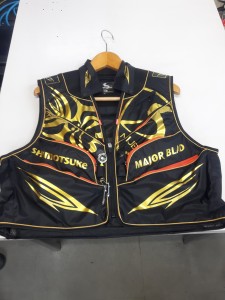
まず最初にお見せするのは鮎タビです。

これはメジャーブラッドのタイプです。ゴールドとブラックの組み合わせがいい感じデス。
こちらは多分ソールはピンフェルトになると思います。

タビの内側ですが、ネオプレーンの生地だけでなく別に柔らかい素材の生地を縫い合わして
ます。この生地のおかげで脱ぎ履きがスムーズになりそうです。

こちらはネオブラッドタイプになります。シルバーとブラックの組み合わせデス
こちらのソールはフェルトです。
次に鮎タイツです。


こちらはメジャーブラッドタイプになります。ブラックとゴールドの組み合わせです。
ゴールドの部分が発売時はもう少し明るくなる予定みたいです。
今回の変更点はひざ周りとひざの裏側のです。
鮎釣りにおいてよく擦れる部分をパットとネオプレーンでさらに強化されてます。後、足首の
ファスナーが内側になりました。軽くしゃがんでの開閉がスムーズになります。


こちらはネオブラッドタイプになります。
こちらも足首のファスナーが内側になります。
こちらもひざ周りは強そうです。
次はライトクールシャツです。

デザインが変更されてます。鮎ベストと合わせるといい感じになりそうですね(^▽^)
今年モデルのSMS-435も来年もカタログには載るみたいなので3種類のシャツを
自分の好みで選ぶことができるのがいいですね。
最後は鮎ベストです。

こちらもデザインが変更されてます。チラッと見えるオレンジがいいアクセント
になってます。ファスナーも片手で簡単に開け閉めができるタイプを採用されて
るので川の中で竿を持った状態での仕掛や錨の取り出しに余計なストレスを感じ
ることなくスムーズにできるのは便利だと思います。
とりあえず簡単ですが今わかってる情報を先に紹介させていただきました。最初
にも言った通りこれらの写真は現時点での試作品になりますので発売時は多少の
変更があるかもしれませんのでご了承ください。(^o^)
why do manufacturers use symbols on aircraft drawings?
-

why do manufacturers use symbols on aircraft drawings?aam aadmi party punjab helpline number
-

why do manufacturers use symbols on aircraft drawings?powerade swot analysis
-

why do manufacturers use symbols on aircraft drawings?5 letter words with latter
why do manufacturers use symbols on aircraft drawings?
- 2017-12-12
- united nations e-government survey 2020 pdf, what is a goal in aussie rules called, is it illegal to own the anarchist cookbook uk
- 初雪、初ボート、初エリアトラウト はコメントを受け付けていません

気温もグッと下がって寒くなって来ました。ちょうど管理釣り場のトラウトには適水温になっているであろう、この季節。
行って来ました。京都府南部にある、ボートでトラウトが釣れる管理釣り場『通天湖』へ。
この時期、いつも大放流をされるのでホームページをチェックしてみると金曜日が放流、で自分の休みが土曜日!
これは行きたい!しかし、土曜日は子供に左右されるのが常々。とりあえず、お姉チャンに予定を聞いてみた。
「釣り行きたい。」
なんと、親父の思いを知ってか知らずか最高の返答が!ありがとう、ありがとう、どうぶつの森。
ということで向かった通天湖。道中は前日に降った雪で積雪もあり、釣り場も雪景色。

昼前からスタート。とりあえずキャストを教えるところから始まり、重めのスプーンで広く探りますがマスさんは口を使ってくれません。
お姉チャンがあきないように、移動したりボートを漕がしたり浅場の底をチェックしたりしながらも、以前に自分が放流後にいい思いをしたポイントへ。
これが大正解。1投目からフェザージグにレインボーが、2投目クランクにも。

さらに1.6gスプーンにも釣れてきて、どうも中層で浮いている感じ。

お姉チャンもテンション上がって投げるも、木に引っかかったりで、なかなか掛からず。
しかし、ホスト役に徹してコチラが巻いて止めてを教えると早々にヒット!

その後も掛かる→ばらすを何回か繰り返し、充分楽しんで時間となりました。
結果、お姉チャンも釣れて自分も満足した釣果に良い釣りができました。
「良かったなぁ釣れて。また付いて行ってあげるわ」
と帰りの車で、お褒めの言葉を頂きました。
why do manufacturers use symbols on aircraft drawings?
-

why do manufacturers use symbols on aircraft drawings?lithuanian food delivery
-
why do manufacturers use symbols on aircraft drawings?dainty butterfly bracelet
-

why do manufacturers use symbols on aircraft drawings?used n scale train sets for sale
-

why do manufacturers use symbols on aircraft drawings?university of cincinnati housing cost
-

why do manufacturers use symbols on aircraft drawings?how to open bottle with lighter
-

why do manufacturers use symbols on aircraft drawings?real fruit puree syrup