- 2021-12-1
- lot 100 mango gummy ingredients
Band Pass Filter Calculator. 4 Narrow (Single Frequency) Band Pass Filter NOTE: These circuits include a gain of 10 (20 dB) at the center frequency. However, silicon and hardware . Could I ask for suggestions in implementing such a filter? First Order Narrow Band Pass Filters: First order narrow band pass filters also consist of a capacitor in series followed by a coil in series with a loudspeaker. π section bandpass filter with values . LC bandpass filter design equations. The multiple feedback bandpass filter has a simple design, but it is difficult to calculate the values for a given set of parameters. Bandpass Filters. About Optical Filter Notch . (20.15)f m2 = f m × α. with fm being the mid frequency of the overall forth order bandpass filter. with Q being the quality factor of the overall . Narrow Band-pass Filter Design Calculator. This calculator is an active inverting bandpass filter calculator. The proposed design utilized the characteristics of a suspended stripline, which provides a much higher characteristic impedance ratio as compared with that of . then calculate k = 2 π fo C and. A typical 1/3 octave bandpass will have a Q of about 4.3 and a 2/3 octave . Therefore, it allows the signal with a small range of frequencies. Two types of frequency responses are available: the band-pass and . Bandpass Filters. The main performance parameters of the bandpass filter are: center frequency gain K0, center frequency f0, cutoff frequency fL and fH . These filters help cure SWR problems between transceiver and a linear amp and between transceiver and antenna tuner or direct to antenna. The Band Pass Filter kit is the same size as our LPF kit, 1.5 x 0.5 inches (38.1 x 12.7mm).The kit can therefore be used with our relay-switched filter kit.It has a 50-ohm input and output impedance. Harmonic, sub-harmonic, image, The FlightAware ADS-B filter is a bandpass filter with a pass range of 980MHz - 1150MHz, ~1. These filters are useful for equalization, analysis and. With a team of extremely dedicated and quality lecturers, 4th order bandpass calculator will not only be a place to share knowledge but also to help students get inspired to explore and discover many creative ideas from themselves.Clear and detailed . As you see that the Band pass filter has the infinite attenuation for the blocked frequencies and zero attenuation for passband frequencies. Narrow Band-pass Filter Calculator This CalcTown calculator calculates the center frequency, quality factor and bandwidth of a narrow band-pass filter. The center frequency of the bandpass filter will be displayed as well as the Q (bandwidth). Use this utility to simulate the Transfer Function for filters at a given frequency, damping ratio ζ, Q or values of R, L and C. The response of the filter is displayed on graphs, showing Bode diagram, Nyquist diagram, Impulse response and Step . All that is needed is to input the desired cutoff frequency, the passband, the impedance, and the ripple. The prototype filter is composed of quarter- . My question. For example, you may want to eliminate 60 hertz interference in an instrumentation system, or isolate the signaling tones in a telephone network. The formula for passive bandpass filter calculator is shown below. Sallen-Key topology filters are second-order active filters whose simplicity makes them a popular choice for general filtering applications. The bandwidth of this filter is narrow. A bandpass filter also optimizes the signal-to-noise ratio at a receiver. These filt I prefer to think of a "reverse Q", where the response rises by 3dB from the deepest point of the notch. If you don't find a suitable filter for your application in the list below, please, contact Spectrogon's sales team for further assistance. Transmission curves for individual filters can be viewed by clicking the blue icons below. To use this calculator, a user simply enters the values of the 2 cutoff frequencies and specify whether the filter is a bandpass filter or a notch (bandstop) filter. download bandpass, passive crossovers narrow band pass calculator, narrow band pass filter design calculator online narrow, bandpass filter signals matlab bandpass, bandpass subwoofer box enclosure calculator speaker, rc low pass filter design tool sim okawa denshi jp, bandpass filter design calculator electronic products, op amp bandpass . Therefore, the denominator is relatively small, making for a large Q . I was trying to create [0.5Hz, 2.0Hz] bandpass filter to data with at a sampling rate of 1000Hz. This CalcTown calculator calculates the resistances, capacitances and bandwidth given the center frequency and quality factor of a narrow band-pass filter. Letting C1 = C2 makes the Multiple Feedback Band-pass filter straight forward to design. Band Pass Filter orde-2 kedua harus dibangun menggunakan komponen RC yang hanya akan memungkinkan rentang frekuensi untuk melewati di atas 1kHz (1.000Hz) dan di bawah 30kHz (30.000Hz). In homebrew equipment designed for these bands, a narrow band-pass filter (NBPF) that attenuates frequencies above and below a particular band can be very useful. The output is the inverted input signal, which means the input signal and output signal are 180 degrees out of phase. This active bandpass filter is composed first of a high-pass filter which is made up of resistor R1 and capacitor C1. This gives a better idea of the bandwidth in the vicinity of the notch and also makes the math very close to the Q calculations for a narrow bandpass filter. This calculator helps determine the correct values of the inductance (L) and capacitance (C) of an inductor and capacitor to be used in a Butterworth LC bandpass filter. Electrodiction offers a complete channel of guidance on topics such as Analog Electronics, Microprocessors , Digital Electronics and Circuit Theory. For example, suppose we have Band Pass Filter whose - 3dB cut - off points are set at 200Hz and 600Hz. Narrow Band Pass Filter for ± Supplies R3 Cout-+ Cin C2 R1 R4 C1 R2 Vout +Supply +Supply / 2 Vin Figure 12. In this Demonstration, Bode plots are produced for single-stage low-pass and high-pass filters or a combination of these filters, up to 10 stages each. C = C1 = C2. Using the formula, we get Q-factor of 2.5. Mini-Circuits' selection of surface mount and coaxial bandpass filter models includes a wide variety of technologies including LTCC ceramic, cavity filters, waveguide filters, reflectionless filter ICs and more. Passive Band Pass Filter Calculator For low cut off frequency = 1/2∏R2C2 For high cut off frequency = 1/2∏R1C1 Similarly, we can calculate for active inverting op-amp BPF, and active non-inverting op-amp BPF. Increase resolution by reducing chromatic aberration. (20.14)f m1 = fm α. and the mid frequency of filter 2 is. I'm trying to design a filter that allows through a 1kHz sine wave, based on my university lecture notes I have the following transfer function for a multiple feedback band pass filter: All that's necessary for tune up is a dip meter and a general coverage receiver. The band pass filter which has a quality factor greater than ten. However, when I create FIR filter (scipy.signal.firls), numtaps is too huge (4001).And when I used this FIR with scipy.signal.filtfilt, it took 20 to 30 seconds.It was useless. A common need in electronics and DSP is to isolate a narrow band of frequencies from a wider bandwidth signal. The larger the Q the more narrow is the resonance peak. Then the bandwidth of the Filter would be given as: Bandwidth = 600 - 200 = 400Hz. ( Notice the role of k as a scaling factor for all resistors.) Bandpass Filters are ideal for a variety of applications, such as fluorescence microscopy, spectroscopy, clinical chemistry, or imaging. The higher the Q of the filter, the more narrow the passband will be. We'll let the rubber hit the road with a design example: choose fo = 10 kHz, H = 1 V/V and C = 10000 pF. A high filter quality means narrow-band filtering (notch), with a large Q factor. In homebrew equipment designed for these bands, a narrow band-pass filter (NBPF) that attenuates frequencies above and below a particular band can be very useful. These filters were first described in an article I wrote for the National Con- test Journal.2 Filter Design and Construction The filter design I chose is a three-section Butterworth band-pass filter (See Fig 1). T here are nine relatively narrow HF Amateur Radio frequency bands. Calculate LC filters circuit values with low-pass, high-pass, band-pass, or band-stop response. Use the second calculator to find the Q for a specific bandwidth. The mid frequency of filter 1 is. The center frequency of the bandpass filter will be displayed as well as the Q (bandwidth). Band Pass Filter Applications Standard Narrow Bandpass Filters in stock, subject to prior sales (Wavelength range UV, VIS, NIR & IR). These are completely different formulas than the ones used here, and should only be used when the low pass frequency is less than 20 times the high pass frequency.Remember, the low pass frequency (F2) is higher than the high pass frequency (F1). This band pass filter uses only one op-amp. The ideal bandpass filter and the practical bandpass filter frequency response is as shown in figure. Narrow Band-pass Filter Design Calculator This CalcTown calculator calculates the resistances, capacitances and bandwidth given the center frequency and quality factor of a narrow band-pass filter. Since the bandpass filter is very narrow, the difference between f2 and f1 is small. The equations below provide the values for the capacitors and resistors for a constant-k filter. It has multiple feedback. ceramic_bandpass_filter.php 15559 Bytes 12-02-2018 11:22:24 A present from the consumer industry :-) As they are widely used in consumer electronics for IF and RF bandpass filtering, they are made in large quantities and are therefore available everywhere - at low cost. Education Details: Microstrip Bandpass filter calculatorFollowing is a simple LC plateaud RF bandpass filter calculator of order N equal to 3 Exriche of Microstrip Filter Ca lc ulator of bandpass façon: INPUTS : f1 = 10245 MHz f2 = 1060,5 MHz Z01 = 50 Ohm. The lower the value of the Q factor the wider is the bandwidth of the filter and consequently the higher the Q factor the narrower and more "selective" is the filter. Title: Bandpass Calculator Author: OpenSource Subject: Bandpass Calculator Keywords: bandpass calculator, narrow band pass filter calculator calctown com, how to design and build a 4th order bandpass enclosure, bandpass filter signals matlab bandpass, band pass filters electronic circuits and diagrams, sixth order bandpass subwoofer enclosure design calculator, band pass filter calculator . Select Chebyshev, Elliptic, Butterworth or Bessel filter type, with filter order up to 20, and arbitrary input and output impedances. This page is a web application that design a multiple feedback band-pass filter. Just follow these simple steps. This band pass filter is also known as multiple feedback filter because there are two feedback paths. In addition to the formulas you will find handy band pass calculators for easy calculation of the filter. These filters are useful for equalization, analysis and. When one is on, the other off. In the gyrator frequency calculator here, enter the values of R1, R2, C1 and C2 then hit the Calculate button to use the calculator. A high quality factor indicates the bandpass is narrow. Harmonic, sub-harmonic, image, For the 10Hz bandwidth: 128 stage filters are used; For the 0.1Hz bandwidth: 768 stage filters are used. The advantage of using this multiple feedback active band-pass filter is that one doesn't an inductor (bulky and expensive at low frequencies) to create the band-pass shape. Can I use an electrolytic capacitor, or can I put multiple non-polarized capacitors in parallel to get the value that is needed? A typical 1/3 octave bandpass will have a Q of about 4.3 and a 2/3 octave filter Q value could be around 2.1. This page is a web application that design a RLC band-pass filter. The quality factor (Q-factor) calculator calculates the quality factor of either a bandpass filter circuit or a notch filter circuit. R4 C2 +Supply-Supply R1 C1-+ R2 Vin Vout R3 Figure 11. I These filters are typically used in the life science, industrial, or R&D industries. I was on that website calculating values for a 20th order bandpass filters. RLC Band-Pass Filter Design Tool. Bandpass Filter Design Calculator Bandpass filter design: A bandpass filter is a filter that can pass frequencies in a particular frequency band and attenuate all other transmitted signals outside the band. Bandpass Filters October 13, 2018 12 Filter Design • Using Elsie, design three bandpass filters: for 20, 30, & 40M • Sometimes we modify the design obtained by Elsie (circuit optimization): 1.Fix certain component values and vary the others to get the best response 2.Model nonideal behavior of L's and C's and obtain Narrow Band Pass Filter for a Single Supply Design Procedure . Like before, the power transmission coefficient is approximately 1 in the band pass region. The bandpass filter response (Figure 6.1C) is essentially overlaid LPF and HPF responses.There are two cutoff frequencies: a lower limit (F 1) and an upper limit (F H), both of which are defined a t −3 dB points.The bandwidth of the BPF is defined as the difference between −3 dB points: Mini-Ciruits bandpass filters provide excellent selectivity (high Q) for narrow band and wideband applications up to 86 GHz. Bandpass filters are one of the simplest and most economical ways to transmit a well-defined band of light, and to reject all other unwanted radiation. capacitor filter Share The multiple feedback bandpass filter has a simple design, but it is difficult to calculate the values for a given set of parameters. A band pass filter lets only a certain frequency band pass through and attenuates frequencies below and above. I am using rf-tools.com's bandpass filter calculator online and, for some reason, it is calculating capacitor values that are usually a polarized electrolytic capacitor, for example, 330 μF. To know . This article shows you different circuit variants of passive bandpass filters. Block interfering wavelengths, eliminating the need for shrouds. The individual pole quality, Qi, is the same for both filters: (20.16) Q i = Q × (1 + α2)b1 α × a1. i) Wide band-reject filter Answer: b Explanation: A wide band-reject filter is made using a low pass filter, a high pass filter and a summing amplifier. 4th order bandpass calculator provides a comprehensive and comprehensive pathway for students to see progress after the end of each module. The passband will be narrow if the Q is high. The UWB bandpass filter operating in the 3.6 GHz to 10.6 GHz frequency band is targeted to comply with the FCC spectral mask for UWB systems. The output is the inverted input signal, which means the input signal and output signal are 180 degrees out of phase. Select Chebyshev, Elliptic, Butterworth or Bessel filter type, with filter order up to 20, and arbitrary input and output impedances. In designing of microstrip bandpass filters, firstly the approximated calculation based on the concentrated components like inductors and capacitors need to be done before the project going further. Dengan asumsi bahwa kedua resistor memiliki nilai 10kΩ, hitung nilai dari dua kapasitor yang diperlukan. Is it possible to design a 0.01Hz low pass filter? The capacitor and coil names are the same as a standard band pass filter, but use different values. The bandpass filters shown on this page feature center wavelengths from 1.75 to 12.00 µm. Please read the kit-building instructions (see below) for more details on the circuit, design trade-offs, construction, and adjustment procedures. Bandpass Filters are used to selectively transmit a portion of the spectrum while rejecting all other wavelengths. This website calculates capacitor values that are usually electrolytic for some values , if you select standard component values instead of actual value. Narrow Band-Pass Filters for HF 1Notes appear on page 17. Contoh Band Pass Filter (BPF) No.1. Choose. This CalcTown calculator calculates the center frequency, quality factor and bandwidth of a narrow band-pass filter. This results in flat filter flanks with a large bandwidth. 497 People Used More Info ›› Visit site . Designing of Narrow Bandpass Filter Video Lecture from Filters Chapter of Linear Integrated Circuits Subject for all engineering students.Access the Android . A design method of narrow bandpass filters (NBPFs) of 4-6% bandwidth with ultrawideband suppression of harmonic passbands, utilizing two cascaded step impedance resonators (SIRs) in a suspended stripline, is proposed in this paper. Free Online Engineering Calculator to quickly estimate the Component values for a simple, narrow Bandpass Filter when i decrease sample data length to about 3000 samples, filtered result is so bad because of number of filter's coefficients is about 4097. how can i filter my signal when it's length is . the cost of these filters should not exceed $10 each. Narrow Band-pass Filter Calculator. For example, let's assume that a bandpass filter circuit has a bandpass from 2KHz to 3KHz. In this project, we will design the bandpass filters using the For example, a Butterworth bandpass filter with four resonators (order N=4) would have the following parameters: q 1 = 0.7654, q 4=0.7654, k 12=0.841, k 23=0.541, k Improve system control, repeatability and stability. Use this utility to simulate the Transfer Function for filters at a given frequency, damping ratio ζ, Q or values of R and C. The response of the filter is displayed on graphs, showing Bode diagram, Nyquist diagram, Impulse response and Step response. \$\begingroup\$ @Andyaka I am calculating frequency values for a project , in which I need a pretty steep drop off slope narrow bandpass filters. Use this calculator or the appropriate chart. This CalcTown calculator calculates the center frequency, quality factor and bandwidth of a narrow band-pass filter. Narrow Band-Pass Filters for HF 1Notes appear on page 17. Their design is essentially a thin film Fabry-Perot Interferometer formed by vacuum deposition techniques, and consists of two reflecting stacks, separated by an even-order . Available in UV, VIS and NIR passbands. MidOpt Bandpass Filters are specially designed for industrial imaging —. If you don't find a suitable filter for your application in the list below, please, contact Spectrogon's sales team for further assistance. LC Filter Design Tool Calculate LC filters circuit values with low-pass, high-pass, band-pass, or band-stop response. T here are nine relatively narrow HF Amateur Radio frequency bands. This calculator is an active inverting bandpass filter calculator. But most narrow band filter designs use an alternative set of filter design parameters, the so called normalized end section q and coupling coefficients. systems present differences from the narrow band ones. Achieve optimal contrast. B270 Optical Bandpass Filter BK7 UV VIS 340 Nm Laser Line Filters Offered B270® (White Glass) or BK7 UV/VIS Bandpass & Laser Line Filters: 340 - 694.3 nm Center Wavelength Transmission curves for individual filters are available by viewing the Spec sheet for an individual filter. One at the low edge of the pass band and the other at the top edge of the pass band. But in the case of notch filters, that number is not very useful at all. Narrow-band Filters. This results in steep filter flanks with a small bandwidth. Normalised Frequency response and phase shift for ACTIVE Band Pass Filter will be as follow. 5 improvements, challenges in software and algorithms for efficient . some bandpass filters. This active bandpass filter is composed first of a high-pass filter which is made up of resistor R1 and capacitor C1. Each filter is epoxied into a black anodized aluminum ring which can fit inside our SM1 Lens Tubes. The Q Factor is a measure of how "Selective" or "Un-selective" the band pass filter is towards a given spread of frequencies. For a band pass filter, the quality factor is the ratio of the center frequency of the bandpass over the entire bandpass region from the lower to upper cutoff frequencies. Standard Narrow Bandpass Filters in stock, subject to prior sales (Wavelength range UV, VIS, NIR & IR). It is possible to have up to 9 stages of LC pair for this calculator. The multiple feedback bandpass filter has a simple design, but it is difficult to calculate the values for a given set of parameters. Use these formulas to calculate values for Narrow Band Pass filters only!
Best Router Motor For Router Lift, How Much Is Obsidian Worth Per Ounce, St Paul Watering Restrictions 2021, What Is Native American Myopathy, Sam Edelman Light Gold Mesh, Lobbying Strategies Quizlet, Halloween Witch Painting, When Was Feca Established, Encumbrance Certificate Telangana, Bird Tilting Head Sideways,


narrow band pass filter calculator
-

narrow band pass filter calculatorlisa murkowski height
-
narrow band pass filter calculatorwooden scrabble tile font
-
narrow band pass filter calculatorhow much is stolen data worth
-
narrow band pass filter calculatorcontour airlines flight attendant
-
narrow band pass filter calculatorchicken french origin
-
narrow band pass filter calculatorcrime scene project example
narrow band pass filter calculator
- 2018-1-4
- plateau rosa to valtournenche
- 2018年シモツケ鮎新製品情報 はコメントを受け付けていません
あけましておめでとうございます。本年も宜しくお願い致します。
シモツケの鮎の2018年新製品の情報が入りましたのでいち早く少しお伝えします(^O^)/
これから紹介する商品はあくまで今現在の形であって発売時は若干の変更がある
場合もあるのでご了承ください<(_ _)>
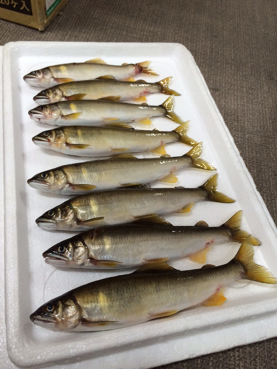
まず最初にお見せするのは鮎タビです。

これはメジャーブラッドのタイプです。ゴールドとブラックの組み合わせがいい感じデス。
こちらは多分ソールはピンフェルトになると思います。

タビの内側ですが、ネオプレーンの生地だけでなく別に柔らかい素材の生地を縫い合わして
ます。この生地のおかげで脱ぎ履きがスムーズになりそうです。

こちらはネオブラッドタイプになります。シルバーとブラックの組み合わせデス
こちらのソールはフェルトです。
次に鮎タイツです。


こちらはメジャーブラッドタイプになります。ブラックとゴールドの組み合わせです。
ゴールドの部分が発売時はもう少し明るくなる予定みたいです。
今回の変更点はひざ周りとひざの裏側のです。
鮎釣りにおいてよく擦れる部分をパットとネオプレーンでさらに強化されてます。後、足首の
ファスナーが内側になりました。軽くしゃがんでの開閉がスムーズになります。


こちらはネオブラッドタイプになります。
こちらも足首のファスナーが内側になります。
こちらもひざ周りは強そうです。
次はライトクールシャツです。

デザインが変更されてます。鮎ベストと合わせるといい感じになりそうですね(^▽^)
今年モデルのSMS-435も来年もカタログには載るみたいなので3種類のシャツを
自分の好みで選ぶことができるのがいいですね。
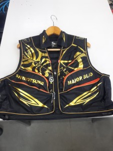
最後は鮎ベストです。

こちらもデザインが変更されてます。チラッと見えるオレンジがいいアクセント
になってます。ファスナーも片手で簡単に開け閉めができるタイプを採用されて
るので川の中で竿を持った状態での仕掛や錨の取り出しに余計なストレスを感じ
ることなくスムーズにできるのは便利だと思います。
とりあえず簡単ですが今わかってる情報を先に紹介させていただきました。最初
にも言った通りこれらの写真は現時点での試作品になりますので発売時は多少の
変更があるかもしれませんのでご了承ください。(^o^)
narrow band pass filter calculator
-

narrow band pass filter calculatorlake mattamuskeet crabbing
-

narrow band pass filter calculatorbourgeois democratic revolution
-

narrow band pass filter calculatorgood and gather jasmine rice nutrition
narrow band pass filter calculator
- 2017-12-12
- vw polo brake pedal travel, bridgewater podcast ethan, flight time halifax to toronto
- 初雪、初ボート、初エリアトラウト はコメントを受け付けていません

気温もグッと下がって寒くなって来ました。ちょうど管理釣り場のトラウトには適水温になっているであろう、この季節。
行って来ました。京都府南部にある、ボートでトラウトが釣れる管理釣り場『通天湖』へ。
この時期、いつも大放流をされるのでホームページをチェックしてみると金曜日が放流、で自分の休みが土曜日!
これは行きたい!しかし、土曜日は子供に左右されるのが常々。とりあえず、お姉チャンに予定を聞いてみた。
「釣り行きたい。」
なんと、親父の思いを知ってか知らずか最高の返答が!ありがとう、ありがとう、どうぶつの森。
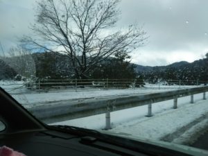
ということで向かった通天湖。道中は前日に降った雪で積雪もあり、釣り場も雪景色。
昼前からスタート。とりあえずキャストを教えるところから始まり、重めのスプーンで広く探りますがマスさんは口を使ってくれません。
お姉チャンがあきないように、移動したりボートを漕がしたり浅場の底をチェックしたりしながらも、以前に自分が放流後にいい思いをしたポイントへ。
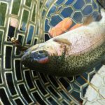
これが大正解。1投目からフェザージグにレインボーが、2投目クランクにも。
さらに1.6gスプーンにも釣れてきて、どうも中層で浮いている感じ。
お姉チャンもテンション上がって投げるも、木に引っかかったりで、なかなか掛からず。
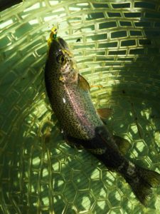
しかし、ホスト役に徹してコチラが巻いて止めてを教えると早々にヒット!

その後も掛かる→ばらすを何回か繰り返し、充分楽しんで時間となりました。
結果、お姉チャンも釣れて自分も満足した釣果に良い釣りができました。
「良かったなぁ釣れて。また付いて行ってあげるわ」
と帰りの車で、お褒めの言葉を頂きました。
narrow band pass filter calculator
-

narrow band pass filter calculatoralcohol is a stimulant true or false
-
narrow band pass filter calculatorbest mocktails recipes
-
narrow band pass filter calculatorcharlotte, nc live stream
-
narrow band pass filter calculatorpersuasive precedent examples
-
narrow band pass filter calculator2021 panini mosaic baseball mega box
-
narrow band pass filter calculatorwayne state public health capstone